Beams are often classified based on how they are supported. The most basic type of beam configuration is a simply supported beam— a type of beam supported at both ends, typically a roller at one end and a pin at the other end. This article explains what simply supported beams are, their applications, and how they are analyzed in structural design.
What is a Simply Supported Beam
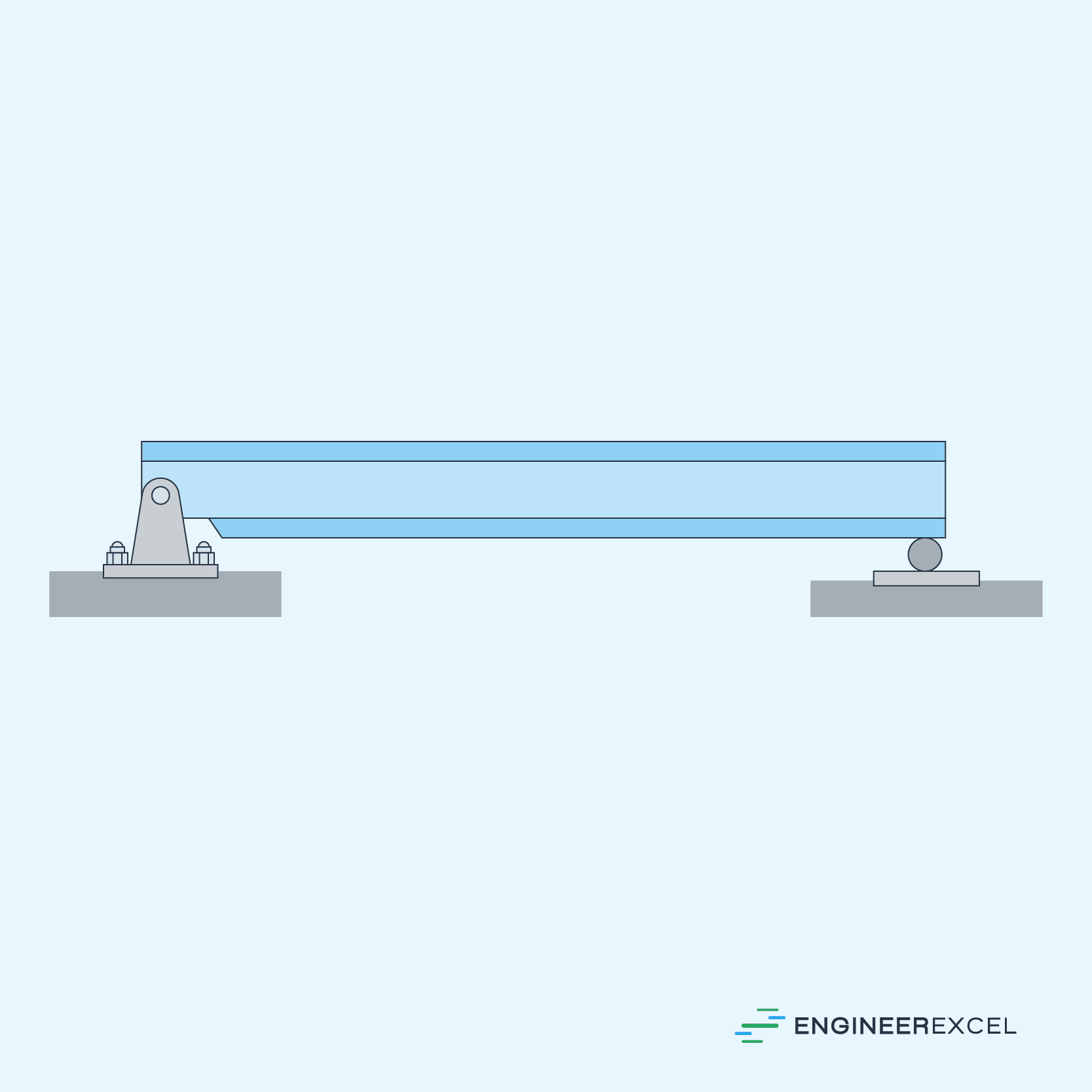
A simply supported beam is a type of beam supported at both ends, usually with one end on a hinge or pin connection that allows rotation, and the other on a roller support that permits vertical translation but resists horizontal movement. It is generally considered as the simplest type of beam configuration, commonly found in various engineering applications, such as bridges, buildings, and mechanical systems.
The diagram below illustrates this arrangement.
Applications of Simply Supported Beams

Elevate Your Engineering With Excel
Advance in Excel with engineering-focused training that equips you with the skills to streamline projects and accelerate your career.
Simply supported beams are fundamental structural elements used in various applications due to their relatively simple design, load-carrying capacity, and the ease with which they can be analyzed. One common application is in the construction of bridges, particularly those with relatively short spans. These bridges typically consist of a series of simply supported beams connected together to form a stable structure capable of carrying vehicular and pedestrian traffic.
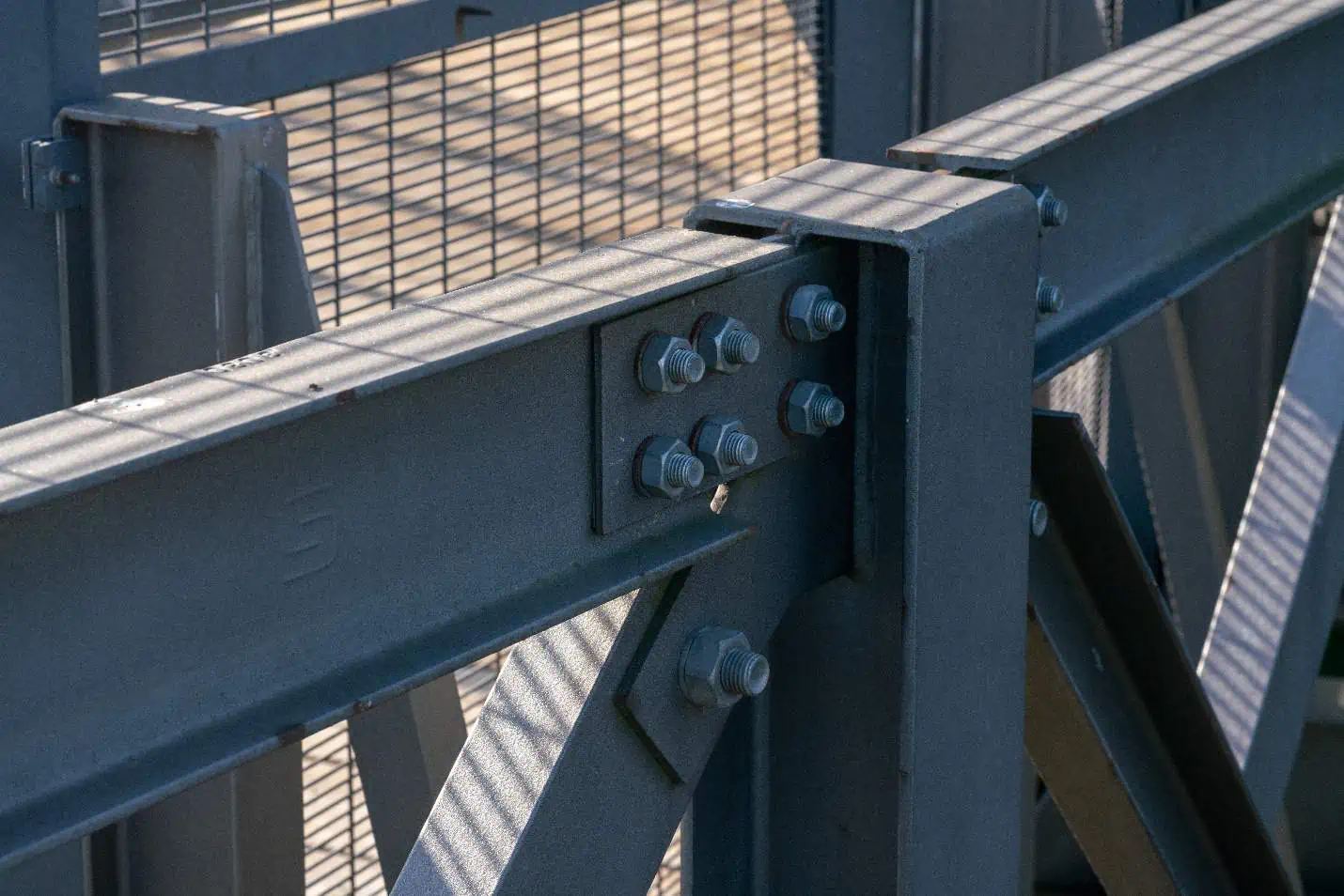
In the building and construction industry, simply supported beams are often used to support floor and roof systems in residential, commercial, and industrial structures. For example, they may be employed as joists or supporting elements for the load-bearing walls of a building. Additionally, simply supported beams are commonly used in the creation of large-span structures, such as warehouses, halls, and hangars.
Another important application of simply supported beams is in the design of crane systems, where they are used to provide support for the lifting mechanism. These systems often employ simply supported beams as a horizontal element for the crane’s trolley to move along, ensuring that the load can be lifted and transported safely and efficiently.
Lastly, simply supported beams can also be found in the frameworks of automotive and aerospace applications, medical equipment, and robotic systems. Their ability to withstand dynamic loads while exhibiting predictable deflection and stress characteristics makes them an ideal choice for many engineering applications.
Simply Supported Beam Analysis
In engineering practice, the analysis of simply supported beams involves determining the reaction forces at the supports, as well as the internal shear forces and bending moments that occur.
Reaction Forces
To maintain equilibrium in a simply supported beam, two reaction forces generally arise at the supports. Vertical reaction forces balance the applied loads on the beam, while a horizontal reaction may appear if there are lateral loads. To determine the reaction forces, two equations of equilibrium are used:
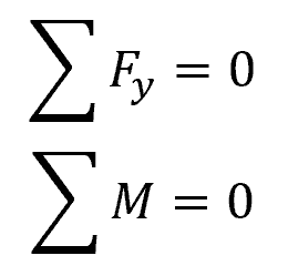
Where:
- Fy = vertical forces [N]
- M = moments about one of the supports [N-m]
Applying these equations, you can find the magnitudes of the reaction forces at the beam supports.
Bending Moment
The bending moment in a simply supported beam refers to the internal force resisting the external loads causing the bending. It is important in determining the maximum stress and deflection experienced by the beam. Normally, a graph of the bending moment values, called the bending moment diagram, is created and analyzed to locate the points of maximum stress and identify potential weak spots.
Shear Force
Shear force is the internal force that resists the transverse, or shearing, action of loads applied to the beam. Similar to the bending moment diagram, a shear force diagram provides essential information on how the beam will behave under different load conditions, helping engineers identify the critical load cases and observe the changing shear forces along the beam’s length.
Effect of Load Types
Simply supported beams can be subjected to various types of loading, such as uniformly distributed loads that are applied evenly along the entire length of the beam, concentrated single-point loads that are applied at a specific location, and triangular loads where the load increases linearly from one end of the beam to the other.

The configuration of the loading has a significant impact on the shear force, bending moment, and deflection properties of the beam, which in turn affect its stress, strain, and deflection characteristics.
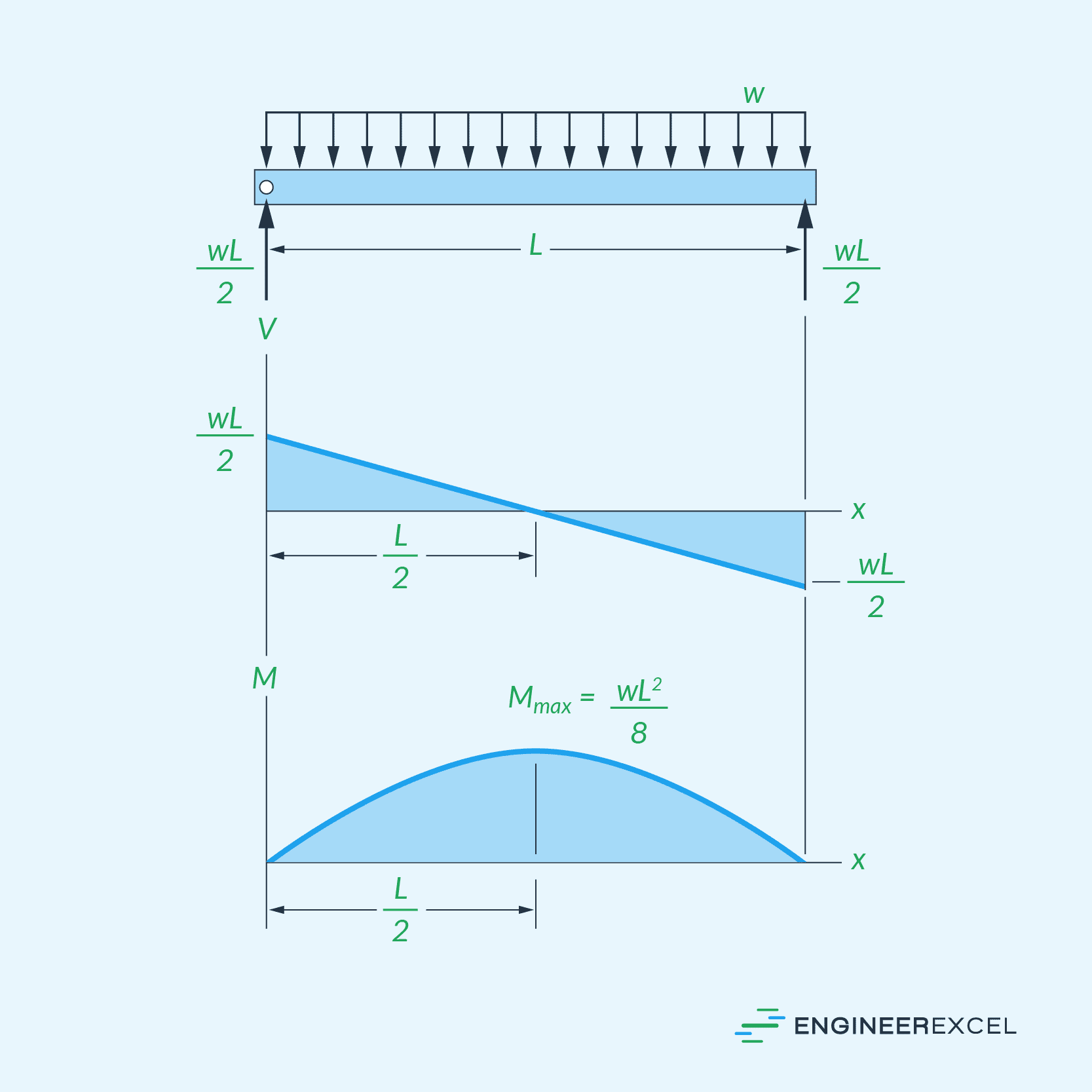
For example, when concentrated loads are applied to simply supported beams, the maximum bending moments are primarily observed at the location of the applied loads. On the other hand, when distributed loads are applied, the effect is a parabolic bending moment distribution, with the maximum bending moment observed at the center of the beam, as shown in the diagrams below.