In
the previous section we completed the design of continuous slabs and beams. All the beams that we considered until now had a rectangular cross section. In this section, we are discussing about beams with another cross section: The 'flanged beams'.
We know that the slabs rest on walls or beams. Consider the case when a slab rests on a beam. In this case, if two 'conditions' are satisfied, a portion of the slab will act as the 'flange' of the beam. That is., when the beam bends, the slab will also bend in the same direction. This is shown in the fig.9.1 below.
Fig.9.1
Slab acting as flange of a beam

The beam will become stronger when it becomes a 'flanged beam' because there is greater concrete area in the upper portion to take up the compression. The lateral stability of the beam also increases. But in order to achieve a flanged section, the following two conditions should be satisfied: The first condition is that the slab and beam on which it rests, should be cast together. The second condition is related to the arrangement of the bars of the slab. This is explained in detail at the beginning of chapter 10 - Design of flanged sections.
T-beams and L-beams are the commonly encountered flanged beams. They are mostly seen in framed structures. Intermediate beams which have slabs on both sides, act as T-beams. The end beams and the beams around staircase or lift openings, which have slabs only on one side, act as L-beams. In both T-beams and L-beams, a portion of the slab acts integrally with the beam. So when the beam bends, this portion of the slab also bends in the same direction as the beam. This portion of the slab is called the Flange and the portion of the beam below the flange is called the Web.
The following presentation gives the basic idea about flanged beams and the effective width of flanges:
An actual building under construction is shown below. The T-beams and L-beams can be clearly distinguished

Equivalent flange width
From the above presentation, we have a basic idea about the concept of 'equivalent flange width' bf . The following properties are associated with bf:
• It increases when the span of the beam increases
• It increases when the width of the web increases.
• It increases when the thickness of the flange increases
• It depends on the type of loading (concentrated, distributed etc.,)
• It depends on the type of support (simply supported, continuous etc.,)
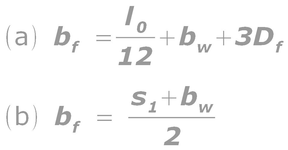
Considering the above factors, the cl 23.1.2 of the code gives the following approximate formulae for calculating bf.
Eq.9.1: for T-beams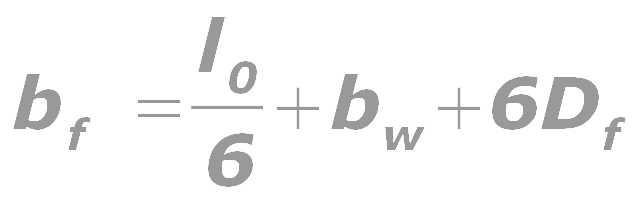
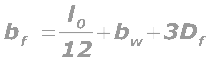
Eq.9.2: for L-beams
In the above formulae, we know that bw and Df denotes width of the web and depth of the flange respectively. But l0 is a new term for us. l0 is defined as 'the distance between points of zero moments in a beam'. When we consider a simply supported T- beam or L-beam, the distance between the points of zero moments in the beam is obviously equal to it's effective span. Because at the supports, the bending moment is zero for a simply supported beam or slab. But this is not the case when we consider a T-beam or L-beam which is continuous over supports, or when it is part of a framed structure. Consider the fig 9.2 below:
Fig.9.2
Portion of the BM diagram of a continuous member
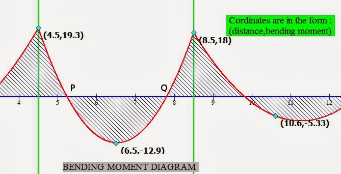
The above fig. shows a portion of the Bending moment diagram drawn for a continuous beam. The moments at supports are of hogging type, taken as positive and so are marked above the X axis. The moments near midspans are of sagging type, taken as negative and so are marked below X axis. Thus there is a transition from positive to negative and then again back to positive when we move along the length of the beam. In the fig, these transitions occur at points P And Q. Each of these points is called a Point of contraflexure, and at these points bending moment is equal to zero. So for the case shown in the fig, l0 is equal to the distance PQ.
The above method to calculate l0 is tedious. So the code permits us to use a much simpler procedure to calculate l0 . This is given as the note below cl. 23.1.2 (c). According to this note, l0 may be assumed as 0.7 times the effective span in continuous beams and slabs. We have already discussed the methods for calculating the effective spans of continuous members here.
So now we know how to calculate bf using eq 9.1 and 9.2. But when we obtain bf of a beam using the above formulae, there is a possibility that we get a value which is greater than what is actually available for the beam in the structure. Given below is fig 9.3 which shows the top right side portion of the structure that we discussed in the presentation. It shows the details of the T-beam P and the L-beam Q.
Fig.9.3
Maximum possible width of flange
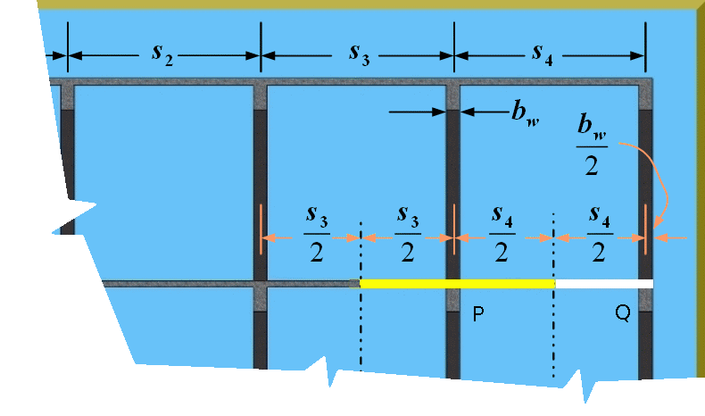
From the fig, we can deduct the following:
Eq.9.3: The maximum share available for the T-beam P (marked with yellow colour) is
Eq.9.4: The maximum share available for the L-beam Q (marked with white colour) is

So the effective flange width calculated using 9.1 should be checked to see that it is not greater than 9.3 and effective flange width calculated using 9.2 should be checked to see that it is not greater than 9.4.
In other words, the lesser value from the two methods of calculation should be used.
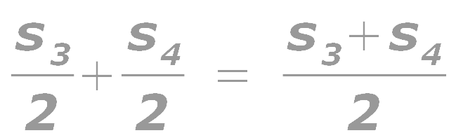
If we denote the center to center (c/c) span on either side of a T-beam as s1 and s2 , and the c/c span on the side of a L-beam as s1 , we can write 9.1 and 9.2 in the general form as:
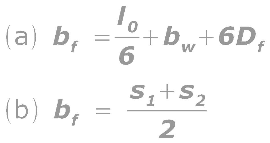
Eq.9.6: For L- beams, bf is the lesser of the following two values:
In some cases, isolated T-beams or L-beams are encountered. Fig 9.4 below shows an example of an isolated T-beam used for a foot bridge. The fig. shows the view from under side of the bridge.
Fig.9.4
Isolated T-beam in a foot bridge
Fig.9.4
Isolated T-beam in a foot bridge

From the fig. we can see that the slab above the beam which acts as the flange, is discontinuous at the sides. The stringer beam of a staircase is another example of an isolated T-beam. A part view of such a staircase is shown in fig.16.84 in the section on transverse stairs. Cl 23.1.2(c) of the code gives the following formulae for calculating for isolated T-beams and L-beams.
Eq.9.7: For isolated T-beams, take lesser of the following two values:
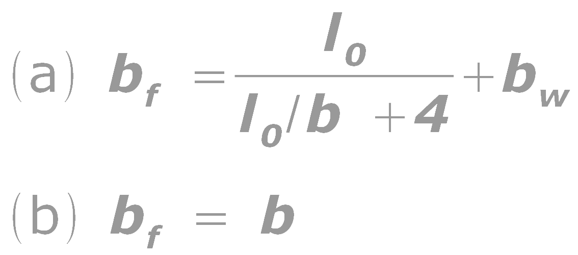
Eq.9.8: For isolated L-beams, take lesser of the following two values:
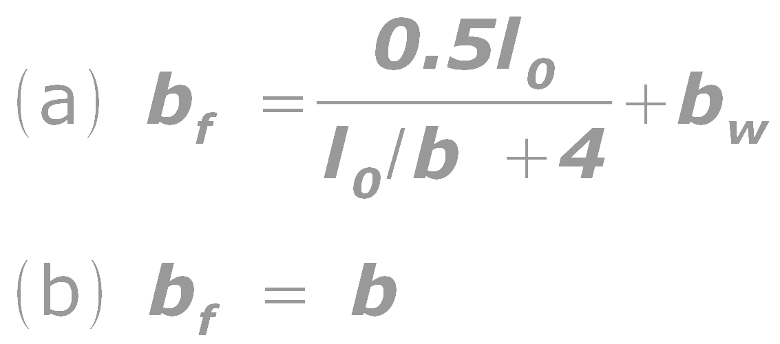
Where b is the actual width of the flange. Obviously, bf cannot be greater than b.
So at this stage we are able to calculate the effective width bf of the flange for different types of T-beams and L-beams. In the next section we will start the discussion on the analysis of these flanged sections.
Copyright©2015 limitstatelessons.blogspot.com - All Rights Reserved
Very interesting and simple to understand
ReplyDeleteThank you very much...
ReplyDeleteSuper information thank u
ReplyDeleteGreat.
ReplyDeleteNice concept.
Nice way to understand the subject
Excellent explanation...
ReplyDeleteamazing
ReplyDeleteExcellent Explanation
ReplyDeleteYou really are able to make something useful for us. You did a great job writing about the Effective flange width of T-beams and L-beams in your article. We're grateful that you took the time to give us this information. Please look at Uns s31000 coil.
ReplyDelete