SAFE ISOLATION AND PROVING DEAD IN ELECTRICAL WORK
Greg Taylor MIET
Senior Electrical Design Engineer & Project Manager at Orbit Electrical Services Ltd.
I recently had the opportunity to write a technical article for #orbitelectrical Services, issued out as a technical publication to all our engineers. Being September and raising awareness for #safe4september within the industry, I have put together an article explaining the correct procedures of safe isolation and parameters to be aware of.
Please feel free to download the article and use it within your own line of work. Sharing knowledge and procedures could define the crucial difference between returning home from that long day at work or not.
Please feel free to share and repost.
#safe4september #safeisolation
Orbit Techincal Publication - Safe Isolation Procedure 2023
Introduction
Safe isolation and proving dead procedures are fundamental in electrical safety. Adhering to local standards such as BS7671 and regulations like the Electricity at Work Regulations 1989 ensures the safety of our workforce and compliance with the law.
2. The Critical Importance of Proving Dead and Navigating Unfamiliar Electrical Terrains
2.1 Dangers of Not Proving Dead Correctly
The act of proving dead is not just a mere procedural step, it is the fundamental principle of working on electrical installations safety. Failing to prove dead properly can lead to:
Electric Shocks: Direct exposure to live parts.
Arc Flashes: A sudden release of electrical energy through the air when high voltage differences exist.
Explosions: In environments with flammable gases or vapours, electrical discharges can ignite these materials.
Equipment Damage: Energised equipment may be damaged during maintenance or repair, leading to costly repairs or replacements.
2.2 Risks with Unfamiliar Switchgear
Unfamiliar switchgear poses unique challenges,
Unknown Configurations: Different manufacturers or older models might have unique installation configurations that are not immediately apparent.
Undocumented Modifications: Previous modifications might not be documented, leading to unexpected live components.
Wear and Tear: Older or unfamiliar switchgear might have deteriorated components over time, making them unreliable and uncommon to competent persons carrying out the isolations.
2.3 Multiple Sources of Supply
Modern electrical installations often have multiple sources of supply for redundancy or specific operational requirements. These can include:
Main Grid Connections: The primary source of electrical power.
Generators: Often used as backup power or for specific operations.
Renewable Sources: Solar panels, wind turbines, and other green energy sources.
Battery Backups: Used to provide uninterrupted power supplies.
The presence of multiple sources means that even if one source is isolated, others can still energise the system. Therefore, it is crucial to identify and isolate all potential sources before beginning any work.
2.4 Concluding Remarks
Knowledge, vigilance, and meticulous adherence to procedures are the best defence against potential hazards in electrical work. Especially when working with unfamiliar systems or in complex configurations, understanding every possible energy source and ensuring they are safely isolated is not just best practice; it's a lifesaver.
3. Delving Deep into the Safe Isolation Procedure (In Steps)
Permission and Planning:
Planning: Conduct a preliminary work area assessment, understand the equipment's layout and potential hazards, and ensure you're equipped with the necessary tools and documentation.
Permission: Depending on the situation and work environment, obtain the necessary permissions to begin the isolation process. In certain scenarios, a formal Permit may be required.
2. Identify Source(s) of Supply and Communication:
Identification: Utilise an approved voltage indicator or test lamp to identify all sources of electrical supply to the equipment or system in question.
Internal Communication: Inform relevant personnel about the impending isolation. This includes team members, supervisors, and other stakeholders who might be affected by the isolation.
External Communication: In situations where there are external stakeholders, such as the Distribution Network Operator (DNO), notify them as required.
3. Verify Tool Functionality:
Before proceeding further, ensure the voltage indicator or test lamp functions correctly. This is crucial to prevent false negatives during the proving dead step.
4. Isolate the Supply(s):
Disconnect the identified sources of supply. Ensure the equipment or system is completely isolated from all potential energy sources.
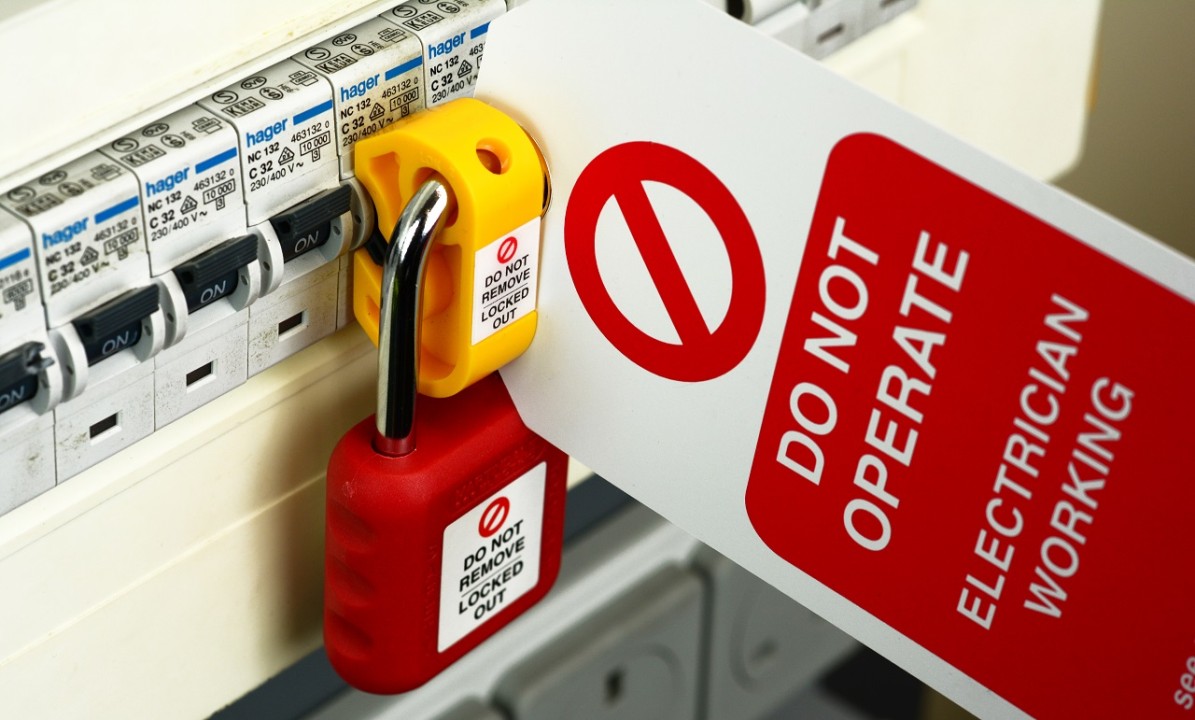
5. Secure the Isolation:
Locking Mechanism: Use appropriate locking mechanisms or devices to secure the isolation points, ensuring no accidental re-energisation during the work.
Key Responsibility: The key to the locking mechanism should remain with the individual who performed the isolation. This person is solely responsible for the isolated system and must have signed the permit. Their possession of the key ensures they have control over the re-energisation of the system.
Multiple Workers Scenario:
Clasp Locking: A clasp lock mechanism should be employed if several individuals are working on the system. This involves using a clasp that multiple padlocks can lock onto. Each worker should have their padlock and key, ensuring every individual must unlock their padlock before the system can be re-energised.
Lockbox Scenario: As an alternative, a single lock can secure the system, with the key placed inside a lockbox. Each worker then places their padlock on the lockbox, ensuring that the system can't be re-energised until every worker has removed their padlock.
Prove the System/Equipment is DEAD:
Confirm that the system or equipment is dead using the previously verified voltage indicator or test lamp.
Re-verify Tool Functionality:
After confirming the equipment is dead, recheck the functionality of the voltage indicator or test lamp using a known live source or a proving unit. This step ensures that the tool is working correctly throughout the procedure.
Warning Signs:
Place clear and visible warning signs at strategic points, notifying others that the electrical installation or equipment has been isolated and work is in progress.
Commence Work:
With all the above steps followed, beginning the required work on the equipment or system is now safe.
NOTE:
An approved voltage indicator or test lamp must comply with the Health and Safety Executive's guidance note GS38. The approved voltage indicator or test lamp must be "proved" using a known live supply or proving unit before and after use to show it is working correctly.
4. Best Practices & Considerations
Routine Maintenance & Checks: As per the Electricity at Work Regulations, 1989, regularly inspect and maintain equipment, tools, and isolation devices.
Documentation & Record Keeping: Maintain isolation logs and equipment manuals, ensuring they're up-to-date with the latest amendments to the BS7671 standard.
Continuous Training & Skill Development: Familiarise the workforce with the latest iterations of the BS7671 and Electricity at Work Regulations, organising periodic training sessions and maintaining personal CPD.
5. Navigating Challenges in safe isolation
Staying Updated: With periodic amendments to the BS7671, it's essential to stay updated.
6. Conclusion
Adhering to rigorous standards and regulations is not just about compliance; it's about ensuring the safety and well-being of our workforce and the general public.
Appendix 1: Safe Electrical Isolation Procedure Flowchart
The flowchart below delineates the sequential steps of the Safe Electrical Isolation Procedure. This visual guide is intended to represent the protocol concisely, facilitating easier understanding and adherence to the process.

Appendix 2: Safe Isolation Permit and Procedure


Appendix 3: Safe Isolation Record Table Example

Appendix 4: Table 537.4 BS7671 Gudeince on the selection of protective isolation and switching devices.


#Safe4September #ElectricalSafety #SafeIsolation #BS7671 #LockoutTagout #ElectriciansUK #ElectricalEngineering #ElectricalCompliance #IsolationProcedures #HealthAndSafety #RiskAssessment #ElectricalWork #ElectricalContractors #ElectricalStandards #SafetyFirst #ElectricalIndustry #ElectricalTesting #IETRegulations #CircuitIsolation #PPE #ElectricalServices
Regional Director
8moDownloaded 🔒😎
Electrical Engineer EngTech MIET
8moThis a nice piece of work.