Steam turbines- Part V- Governors
Few days ago, I had a discussion with my colleague regarding the mechanical and electrical governors in steam turbines. I’ve done a bit of research and the results worth spreading. As usual I will start this article with a brief introduction.
Governors in steam turbines
Among different compartments of steam turbines, governor is a device that controls the turbine speed. Governors divided into two major categories based on their construction features; mechanical and electrical. Governors are the main component of control system of each turbine train. Main purpose of governors are to be used during normal operation. As turbine speed increases above the limits that OEM (Original Equipment Manufacturer) declared, another mechanism called “Over Speed Protection” will seize the turbine operation.
The Speed Governor provides operational control AND primary over speed protection. Due to the dire consequences of a turbine over speed, there should be a "SEPERATE & DIVERSE" Emergency Over Speed Governor that will trip the turbine in the event the Speed Governor fails to provide over speed protection in an over speed event . (Credit goes to Mr.Byrd)
Governor parts
In the next parts of this chapter, major parts of governors are described. Both mechanical and electrical turbines have these parts in common despite the difference in manufacturing procedure.
1- Sensors
In order to control the turbine speed, governors shall first sense the current speed. In mechanical governors this sensor are mechanical elements such as a coupling connected to a flywheel. In electrical governors, this sensor can be a proximity speed sensors.
2- Comparison logic
Every governor has a set point. Set points are set by OEM or operator based on process requirements. In the logic section, current speed of turbine sensed by sensors is compared with the set point value. If the differential value of set point and current speed, exceeds the higher limit or falls below the lower limit, the logic will issue a corrective order. In mechanical governors pilot valve plunger together with flywheel will compare and issue the order for the actuator. In the electrical governors on the other hand the logic chipset of governor will do the comparison.
3- Actuator
Upon receiving the order from the logic section, actuators are acting to correct the speed of turbine. Actuators can be a motor for electrical governor or the plunger valve and a lever that opens/closes the valves by using the pressurized hydraulic oil.
4- Valves
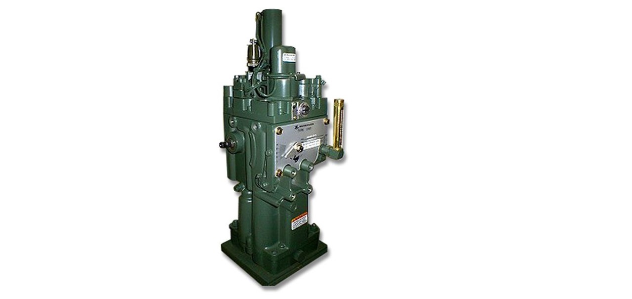
Valves are used to open or close the steam stream. By changing the steam flow, the speed of turbine will be changed. As mentioned in previous chapter, governor system and over speed protection system (or trip system) are two completely different systems both acting on inlet steam stream. In some turbine manufacturer design governor valve and trip valve can be a same valve, meaning that one valve for both trip and governing the turbine speed. This valve is called “TRIP-THROTTLE VALVE”. On the other hand, other manufacturers use two separate valves. These valves are installed in series at the turbine inlet pipeline. Figure 1 shows a combined T&T valve, courtesy of Schutte and Koerting. Contrary to trip valve having only two position of fully open (during normal operation) and fully closed (during emergencies), governor valves can operate in partially open positions as well. Actually most of the time governor valves are partially open.

Figure 1- Combined T&T valve
Working principal
Basic working principal of different types are governors are same. Governor sensors sense the rotating speed of turbine shaft and compares this speed with set point speed. If the differential value exceeds the higher limits or below the lower limit, logic will issue a command to actuator to close or open the governor valves.
Mechanical governors working principals
A typical mechanical governor system is showed in figure 2. As stated in H.P.Bloch book (reference No.1)
Motion of the flyweights depicted in Fig. 1 causes the pilot valve plunger to change the power piston oil pressures, producing movement of the terminal shaft that is connected to the balanced, double-seated valve through linkage and a single lever.

Figure 2- Mechanical governor typical parts. Courtesy of H.P.Bloch, Ref.1
Electrical governors working principals
For the electrical governors, two speed probes are installed on the turbine shaft. The probes are proximity type usually, meaning that the probes are not in direct contact with the rotating shaft. These probes transmit the speed to governor logic. The logic compares the actual speed with set point and issues a corrective command if needed. If corrective command issued, the governor valve will be closed or opened by using a motor.
Proximity speed probes sense the change in magnetic field. They are divided in to different categories. A common type of sensors are HALL EFFECT SENSORS.
The "prox" probe has its own magnetic field from the supplied high frequency excitation. the ferrous metal of a tooth passing through this small area field causes a disturbance that is detected in the prox probe and transformed into an electrical signal proportional to the gap of the passing tooth. the magnitude of the electrical signal generated by the passing tooth is not effected by the rotational speed of the tooth and thus the signal profile stay the same from turning gear to over speed.a reluctance probe has a permanent magnetic field wrapped with wiring coils. It generates an electrical signal that is proportional to the speed of the passing tooth. thus for practical purpose there is no speed signal while on turning gear, but the probes signal magnitude become usable when speed increases. (Credits goes to Mr.Byrd)
The other type of sensor is Variable Reluctance speed sensor. As illustrated in Figure 3, a magnet is installed on one of the teeth of the gear. This gear installed on the shaft for the speed sensing purpose. The proximity sensors can sense the magnetic field of this magnet. As the magnet passes below the proximity sensors, a pulse is generated in the probe. Counting number of these pulses can show the turbine rotating speed. These mentioned sensor types are not the only used sensors. Other types include:
- RF (eddy current) Speed sensors
- Amplified (active) Speed sensors
- Preamplifiers Speed sensors
Hall effect sensors are most widely used type of sensors. For further reference MOTIONSENSOR website provides a good reference.
I mentioned two probes. One probe is enough for sensing speed; however, two is used for the safety and maintenance issues. If one of the probes fails, based on safety routine either there is no need to trip the package at all and operators can wait for next plant overhaul OR they can follow the shutdown sequence causing much less damage to package/plant rather than an emergency shutdown.

Figure 3- Variable Reluctance Proximity sensor operation illustrated- Courtesy of API 670.
Governor Precision
Mentioned in previous chapter, in the both types of governors, the current speed is compared to set point and if there is a difference, the governor will issue the related command. But it does not make sense for governors to issue a corrective order if the difference is below a certain limit. These limits are stated in different standards, but the widely used standard is NEMA23. A term shall be defined here. DEAD BAND is a term used in governors articles. As per NEMA 23 definition Dead band is the total magnitude of the change in steady state speed within which there is no resulting measurable change in the position of the governor controlled valve(s). It is a measure of the speed governing system insensitivity and is expressed in percent of rated speed.
In NEMA23 standard there are 4 classes stated for governor precision illustrated in the figure 4.

Figure 4- Governor precision class according to NEMA SM23 Standard.
As it is mentioned Classes varies from Class A to Class D. Class A governors has a higher degree of freedom meaning they are less sensitive to turbine speed changes. They are used in less important devices such as turbine driven pumps, fans and etc. On the other hand class D has a very restricted range of operation allowing only small variation in speed. Class D is used in critical equipment such as main compressor, cooling water pumps and etc.
A graph of speed variation for Class D governor is showed in the figure 5 for ease of understanding. Upper and lower lines show the dead band. Governor will not take action while the current speed of turbine differs below +-0.25% of set value. But if the speed exceeds 0.25%, the governor will issue an order to actuator to closes the governor valve. Same goes if turbine current speed drops below 0.25% line, governor valve will be opened.

Figure 5- Turbine speed variation in a governor according to NEMA SM23 class D- Courtesy of NEMA SM23 Standard.
Brief on different classes of governors
- Class A: mechanical governors are the old fashioned flyweight governors. As the speed increases above due to centrifugal forces weights move further from each other. For speed decrements it is vice versa, flying weights close the gap. This movement of weight ball cause the shaft (red vertical line in figure 6) to move upward or downward and directly closes/opens the governor. This class is used in small turbines.

Figure 6- A very simple illustration of flying weight. (Credits go to Mr.Byrd)
- Class B: Direct acting orifice-A shaft driven, positive displacement type oil pump delivers pressure to a spring loaded diaphragm connected to the governor valve stem. Since the delivered oil pressure is directly proportional to shaft speed, control can be accomplished. This design is seldom used in modem turbines.
- Class C: Is similar to class A consisting of self-contained flyweight.
- Class D is discussed in next chapter in more detail.
Mechanical vs. Electrical governors
Mechanical governors are cheaper than electrical governors. Mechanical governors do not require any electrical source, thus more reliable. The only required power mechanical governors need is hydraulic which can be provided from sources like lube oil unit. One may argue that lube oil unit needs electrical power itself, thus mechanical governors indirectly requires power. This issue can be solved by using shaft driven lube oil pump and a reservoir. With the combination of shaft driven lube oil pump, an oil rundown tank and mechanical governor, turbine drives will be almost pure mechanical equipment.
On the other hand electrical governors require electrical power, but it is much cheaper and easier for electrical governors to be precise, meaning uses higher classes of NEMA SM23 compared to mechanical governors. As mentioned in previous chapter, Governors, mechanical or electrical, can be according to NEMA 23 Class A, B, C or D.
Due to manufacturing faults, and nature of mechanical compartments, it is hard and costly to manufacturer a mechanical governor with higher class NEMA such as NEMA D.
Specifically for NEMA Class D mechanical governors following issues exist
- Class D oil relay mechanical governors: They typically used in 50s to 70s. They had a very high maintenance cost and time. Maintenance were tremendous amount of work since operator needs to correct wear in many parts such as linkage, pins, bell cranks and etc.
- Class D Precision oil relay: this system invented by one of manufacturers in the US (I guess WOODWARD but it shall be checked across references). In this system, mechanical governor employs a separate hydraulic system. Maintenance are less time consuming than old fashioned Class D mechanical governor but the governor needs to be checked after each test and twice a year. In this type of governor wearing is still a problem.
- Class D Electrical governors: This the NEMA class used widely for electrical governor. It uses proximity speed probes. Since the precision of electrical equipment are higher than mechanical parts and cheaper to manufacture, Electrical governors are widely use with NEMA D classes.
Final words
I wrote this (semi) long article to come to this section; while it is accepted to have Class A electrical governor and Class D mechanical governor, they are not used and manufactured in this way due to economic reasons.
Mechanical governors are used with NEMA23 classes A, B and C, since they are cheaper and more reliable with less initial and maintenance costs. On the other hand electrical governors are used based on NEMA class D in the critical applications where turbine speed variation is not acceptable and it can cause huge damage to production, such services can be SYNTHESIS GAS compressor or cooling water pumps in petrochemical plants both with turbine drives. In any of these cases (I had experience on both of them) slightest turbine variation can cause halt production for brief time or even a plant trip.
Special mention
Internet changed the world a lot. I do not want to lecture on how internet changed the world but how it changed mine. During the course of writing these articles, I've learnt a lot. One of the people that taught me so many points and help me polish my articles is Mr.J.F.Byrd. I really appreciate his selfless help.
Related Articles
References
- Heinz P. Bloch and Murari P. Singh, 2nd Edition. "Steam turbines: Design, Application and Re-Rating" Mc Graw Hill. 2009
- NEMA standard pulication No. SM23-1991
- William E.Nelson and Perry C.Monroe "Understanding and Preventing Steam Turbine Overspeed", PROCEEDINGS OF THE 26TH TURBOMACHINERY SYMPOSIUM
- API 670, 4th Edition, "Machinery Protection Systems"
#governor #control #mechanicalgovernor #electricalgovernor #nema23 #woodward
SENIOR ELECTRICAL ENGINEER at ULTRATECH (ABG)
2ySir plz share the previous chapter of steam turbine parts
Vertriebsingenieur bei Emerson Schweiz I Techniker HF Energie- und Umwelttechnik I Funktionale Sicherheit Ingenieur (TUV)
5yVery interesting topic, thanks for sharing this article!
P.hd. Automation & Instrumentation Expert & Trainer
5yVery good intro on governors' type and precision. Thank you.
with sharing and discusion to elavate the knowledge
5yNice of knowledge sharing and a part of KM'er behaviors.