Transformer maintenance and repair methods
The transformer is a device that uses the principle of electromagnetic induction to change the AC voltage. The main components are the primary coil, the secondary coil, and the iron core (magnetic core). The main functions are: voltage conversion, current conversion, impedance transformation, isolation, voltage regulation (magnetic saturation transformer) and so on. According to the application, it can be divided into: power transformer and special transformer (electric furnace change, rectification change, power frequency test transformer, voltage regulator, mine change, audio transformer, intermediate frequency transformer, high frequency transformer, impact transformer, instrument transformer, electronic transformer , reactors, transformers, etc.).
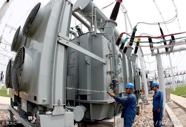
The maintenance of the transformer is the daily work that the electrician operator and the electrician's operation and maintenance personnel must perform in order to maintain the normal technical state of the transformer and prolong the service life. Maintenance of transformers is an important part of electrical equipment management. If the maintenance work is done, it can not only reduce the equipment failure rate, save maintenance costs, reduce costs, but also bring good economic benefits to the company and employees. So what are the things we need to pay attention to when repairing and repairing transformers?
First, the capacity
In normal operation, the load on the transformer should be about 75-90% of the rated capacity of the transformer.
Second, the temperature
The thermometer installed on the transformer should be recorded at the same time when patrolling the transformer. The unattended transformer shall record the voltage, current and upper oil temperature of the transformer at each periodic inspection. In addition, for distribution transformers, the load of a certain three-phase should be measured during the maximum load. If the distribution is unbalanced, it should be redistributed. The period of measurement shall be specified in the site regulations
Third, insulation monitoring
The insulation resistance of the coil shall be measured before the transformer is put into operation after installation or maintenance (usually after drying) and after long-term deactivation. The measured value and the oil temperature during the measurement shall be recorded in the transformer history card.
The insulation resistance of the measuring coil should be a megohmmeter of 1000 to 2500 volts. The allowable value of the coil insulation resistance is not specified.
The ratio of the measured insulation resistance value during the use of the transformer to the value measured before the transformer is put into operation after installation or overhaul is the main basis for judging the insulation state of the transformer during operation. The measurement of the insulation resistance should be carried out at the same temperature as possible, using the same megohmmeter of the voltage.
Fourth, the current range
The maximum unbalance current of the transformer low voltage shall not exceed 25% of the rated value; the allowable range of transformer power supply voltage variation is plus or minus 5% of the rated voltage. If this range is exceeded, the tap-changer should be used to adjust the voltage to the specified range.
(The power should be cut off during adjustment.) It is usually to change the position of the winding tap of the winding to realize the voltage regulation. The device for connecting and switching the position of the tapping tap is called the tap changer. It adjusts the ratio by changing the number of turns of the high voltage winding of the transformer. of.
The low voltage has no effect on the transformer itself, only reduces some output, but has an impact on the electrical equipment; the voltage increases, the magnetic flux increases, the core is saturated, the core loss increases, and the transformer temperature rises.
Five, overload
In special cases, the transformer can be overloaded for a short period of time, but it should not exceed 30% of rated load in winter and 15% of rated load in summer. In addition, the overload capacity of the transformer should be determined based on the temperature rise of the transformer and the manufacturer's specifications.
The overload is divided into normal overload and accident overload. The normal overload is caused by the increase in power consumption of the user under normal power supply conditions. It will increase the temperature of the transformer, causing the transformer insulation to age and the service life is reduced. Therefore, overload operation is generally not allowed.
There are many types of faults in transformers, but common fault phenomena are not limited to short circuits, open circuits and leakage. The reasons for these failures can be summarized into three aspects: one is that the design is wrong; the second is that the production quality is poor; the third is that the use conditions exceed the design requirements.
Transformer maintenance method: The first step is to disassemble the core. Transformers are often filled with asphalt, wax and other materials. They should be heated to disintegrate them from the transformer before disassembly. In addition, the transformer leads should be welded off the terminals, the fixing splint should be removed, and the first silicon steel sheet should be picked up with a screw driver, and then the pliers should be removed. Pull the silicon steel sheets one by one. Care must be taken when removing the silicon steel sheet, not to damage the coil leads, and to avoid breaking and bending the silicon steel sheet. The removed silicon steel sheets are then collected and wrapped in paper to avoid loss and damage to the insulation. 20
The second step is to remove the coil. After taking out the core, first check the appearance of the coil to see that the appearance is not damaged, and then use the insulation resistance meter to check which coil the fault occurred in order to be purposefully disassembled. When disassembling, pay attention to the insulation between the layers, the diameter of the wires, the number of turns per layer and the number of layers, etc., so as to refer to the rewinding. At the same time, care should be taken to protect the skin of the wire insulation paint for reuse; special care must be taken to find and find the cause of the coil short circuit and open circuit. When the faulty part is found and processed, it can be re-wound according to the original winding method, and after the winding and repairing, comprehensive testing and inspection can be carried out. It can only be used after all the indicators meet the requirements.
Collection by Simon Liu
Director of International Core Business Center at Jinte Company---Focus on【Aluminum & Copper Strip Coil of Transformer】
Email:simon@jintetech.com
Calling:+86 0572 8022080
Mobile/Whatsapp:+8618906728277
Wechat:simon1900928110
Skype:kinghong2012
Tweet: osmuntech
Authorized by:
Zhejiang Jinte New Material Technology Co., Ltd
Suzhou EU Metal Co.,Ltd
Interim Management - Sales & Marketing - Strategic & Consultative Selling, Project Management
5ysuper!!!