
Characterising Modal Behaviour of a Cantilever Beam at Different Heating Rates for Isothermal Conditions


1
School of Aerospace, Transport and Manufacturing, Cranfield University, Bedford MK43 0AL, UK
2
Aerospace Engineering Department, Khalifa University, Abu Dhabi P.O. Box 127788, United Arab Emirates
*
Author to whom correspondence should be addressed.
Appl. Sci. 2021, 11(10), 4375; https://doi.org/10.3390/app11104375
Submission received: 15 April 2021
/
Revised: 7 May 2021
/
Accepted: 9 May 2021
/
Published: 12 May 2021
(This article belongs to the Collection Nondestructive Testing (NDT))
Abstract
:The effect of temperature on structural response is a concern in engineering applications. The literature has highlighted that applied temperature loads change the system vibration behaviour. However, there is limited information available about temperature impacting the dynamic response. This paper investigated the heating rates effects on modal parameters for both with crack and without crack conditions in a cantilever beam. A beam subjected to three heating rates was considered: 2, 5, and 8 °C/min. The first one was assumed as a slow heating rate while the others were assumed as moderate and high, respectively. This controlled rate of heating was achieved by using a proportional-integral-derivative (PID) temperature controller. The results showed that heating at different rates has little impact on modal parameters. While this effect is minimal at lower temperatures and more evident at higher temperatures. The results of temperature ramped at 2, 5, and 8 °C/min were compared with the numerical and analytical results only for all the isothermal conditions. It was observed that the beam natural frequency and its modal amplitude decrease with the increase in temperatures and crack depths. Therefore, it is concluded that the rate of heating can make a slight impact on the dynamics response of any mechanical system.
1. Introduction
Vibration-based inspection of mechanical structures for structural health monitoring is widely studied [1,2,3]. However, many engineering practical applications such as automotive, aircraft, power plants, etc. operate in the thermal environment along with the mechanical loads. Especially, during the heating and cooling process of the thermal systems, the vibration response may vary significantly. Published research methods are infeasible to capture the addition of thermal disturbances. The rate of heating and temperature exposure duration may vastly affect the system response, especially during crack growth. Under coupled loads, the dynamic response of the structure is subjective by the mechanical and thermal loads [4]. The change in temperature in the structure fluctuated the vibration centre and eigenfrequencies. The vibration response in such conditions is the combined effects of thermal, loading mode, material properties, and boundary conditions [5,6]. The temperature change alters the fundamental frequency of the system [7,8].
The mechanical structures which operate in cyclic loads for a long duration generate heat on the system apart from the applied thermal loads. This change in global temperature affects the intensity of stress concentration which consequently modifies the structural dynamic response [9]. Therefore, the thermal effect and its distribution on vibrating structures are the focus area of research [5,6,10,11,12,13,14,15,16,17,18,19]. The thermal vibration and thermal expansion behaviours are apparent due to the increase in interatomic bond length at elevated temperatures [10]. Zhang et al. [16] studied the thermal effect on the beam using the energy flow method. Their investigation underlined that the thermal vibration increases with an increase in temperature mainly derived from thermal loads and changes in material properties. In the same way, the thermal effect on the vibration behaviour of functionally graded material influenced the natural frequencies at high temperatures [14,15]. Cui and Hu [17] observed that temperature-dependent material properties have little influence on the natural frequency at low temperature. However, there was a large influence when the temperature increased. Fazzolari [20] studied the temperature-dependent material properties under thermal loads on functionally graded material. They noticed that there was an attenuation rate of dimensionless frequency at high temperatures. Silva et al. [18] investigated modal analysis in a non-uniform temperature distribution heated rectangular plate with the help of digital image correlation. They found that resonant frequencies of the plate were higher for transverse heating than longitudinal heating. Kawamura et al. [21] observed that a decrease in Young’s modulus at varying temperatures decreases the vibrating amplitude.
In the literature, the vibration or dynamic response of cracked structures has been investigated by different approaches [2,22,23,24,25,26,27,28,29,30,31,32,33,34,35]. However, the existing research on crack growth did not consider the effect of the rate of heating with different temperature exposure times. When the mechanical structure is exposed to high temperatures for a long duration, it may modify the mechanical properties of the material and hence influence the structural dynamic response. Furthermore, the dynamic behaviour of the structure depends on many factors associated with the applications and design. In this paper, the modal response of the structure is evaluated in the presence of thermal and mechanical loads. It investigated the heating rate’s effect on modal parameters for both with crack and without crack conditions in a cantilever beam. A beam subjected to three heating rates was considered: 2, 5, and 8 °C/min. The first one was assumed as a slow heating rate while the others were assumed as moderate and high, respectively. This controlled rate of heating was achieved by using a proportional-integral-derivative (PID) temperature controller. The results showed that heating at different rates has little impact on modal parameters. While this effect is minimal at lower temperatures and more evident at higher temperatures. The results of temperature ramped at 2, 5, and 8 °C/min were compared with the numerical and analytical results only for all the isothermal conditions. It was observed that the beam natural frequency and its modal amplitude decrease with the increase in temperatures and crack depths. Therefore, it is concluded that the rate of heating can make a slight impact on the dynamics response of any mechanical system.
The paper is organized as follows. In Section 2, the analytical modelling to evaluate the modal response of a cantilever beam considering the accelerometer mass and effective length of the beam is defined. Section 3 describes the details of the experimental set-up and procedure for modal analysis of the cantilever beam. Section 4 presents the numerical simulation. Section 5 provides the results and discussion. Section 6 contains the conclusions.
2. Analytical Modelling
2.1. Modal Response for a Cantilever Beam
We considered a Bernoulli-Euler beam theory for structure in fixed free-boundary conditions with a uniform cross-section, as shown in Figure 1. The transverse vibration force was applied at the fixed end with an accelerometer mass at the other end. Let L be the length, is the axial expansion of the length due to thermal expansion. Therefore, is the effective length, B is the width, and h is the thickness of the beam. The beam is considered in one-dimensional longitudinal expansion only because the dimensions B and h are relatively small compared to the beam’s length. The inertia force in the beam element can be expressed using the free-body diagram as:
where represents the transverse displacement, is the mass density of the beam, is the cross-sectional area, and is accelerometer mass.
The shear force equation for the beam element can be written as:
where , Similarly, the moment equation for beam can be written as:
where . The shear force and moment equations reduce to Equations (4) and (5), respectively:
The force equation can be written in term of displacement and transverse force as:
The relation between the bending moment and transverse displacement is expressed using the Euler-Bernoulli beam theory as:
where is the elastic modulus and is the moment of inertia of the beam. When the beam has a uniform cross-section, the equation of the vibrational beam can be transformed as:
For free bending vibration, the applied force is zero, therefore, the equation is reduced to Equation (9):
The solution of Equation (9) can be obtained through a separation of dependent variable method expressed as:
Thus, the free vibration equation of the beam can be deduced in the form of a separable variable method as Equations (11)–(13):
Let be constant:
Separating the time and spatial variables respectively, we have:
The solution of Equation (15) can be written as:
The solution of Equation (17) is satisfied if:
The solution for vibration mode, Equation (17) is assumed as:
where are constants that can be obtained by applying the boundary conditions. The boundary conditions of the fixed-free beam are:
And
Applying the first boundary conditions, we get:
Therefore, the harmonic solution can be rewritten using Equations (21) and (22) as:
Since the bending moment and shear force is zero at , we have from the second boundary condition:
Forming Equations (28) and (30) into matrix format, we have:
Solving Equation (31), we obtained the characteristic Equation (32). The subscript is added because multiple roots satisfy the equation.
The roots of the Equation (32) are:
for n = 1
for n = 2
Therefore, the circular frequency of the beam can be expressed by rearranging Equation (19) as:
The modulus is a temperature-dependent property that varies with respect to temperature. The modulus decreases with increasing thermal energy along the beam. This decrease is assumed as being linear with temperature. The approximate relationship [36] is given in Equation (36):
where is the proportional constant, is the melting temperature, and is the temperature at the measured value of , and is the modulus at 20 °C. Hence, Equation (35) can be written as:
The bending moment equation of the beam considering the temperature dependent elastic modulus can be written as:
where is the load amplitude at time . The total deformation energy (Q) due to the beam deformation is derived from the direct bending moment equation.
where
The strain of the beam is dependent on applied stress and temperature. Therefore, we can express strain as a function of stress and temperature as Equation (44):
where and
While and are variation in strain due to stresses and temperature respectively. The direct strain of the beam can be found by integrating Equation (46) for uniform temperature with linear thermal expansion.
2.2. Heat Conduction Equation
The heat conduction equation for a one-dimensional system is estimated based on Fourier’s law expressed as Equation (47):
And the heat flux along the beam can be calculated as:
where is the thermal conductivity, , is the power (in watts) which is supplied to heat the beam, is the thickness of the beam, is the cross-section area of the beam, and is the effective length of the beam.
2.3. Equation of Dynamic Response of the Beam under the Crack Condition
Changes in the deformation energy and natural frequencies due to crack can be computed from the bending moment and flexural rigidity [37]:
where is the stiffness of the crack beam represented by Equation (50):
where is the crack function and is the crack depth. Change in the natural frequency due to the crack on the beam can be found as:
Therefore, the new natural frequency of crack beam can be computed from Equation (53):
The modal amplitude of the cantilever beam was analysed using Equation (10). The amplitude is dependent on the respective fundamental frequency of the without crack and with crack beam. Therefore, the fundamental frequency of the without crack specimen was obtained from Equations (37) and (53) for a with crack beam.
3. Experimentation
3.1. Specimen Properties and Preparation
Experimental specimens were prepared from aluminium 2024-T3. The thermal and chemical properties of the material are given in Table 1 and Table 2, respectively. The elastic modulus was measured with a dynamic mechanical analyser and thermal expansion was measured using a thermal-mechanical analyser. The thermal conductivity was calculated from the relation of thermal diffusivity as given in Equation (54). The thermal diffusivity was extracted from [38].
where is the thermal diffusivity, is the density, and is the specific heat.
Figure 2 shows the geometry of the specimen. In this analysis, four types of specimen: no crack, and 0.25, 0.5, and 1 mm crack depth of rectangular size were selected. The predefined crack depth was selected on the criteria that the initial crack dept was 0.25 mm and propagated to 1 mm. The location of the crack is the same for all crack depths which is 4.5 mm away from the fixed end. This location was selected, based on the specimen design, to have a maximum stress concentration at the fillet area. The specimen had four holes of 6 mm diameter for mounting on the mechanical shaker and another hole of 2.5 mm diameter was provided for the accelerometer at the other end. The specimens were made by a computer numerical control (CNC) machine to produce accurate dimensions.
The experiment was designed to analyse the modal characteristic of the predefined crack and without crack beam under uniform temperatures in the range of 25 to 200 °C. A beam subjected to three heating rates, i.e., 2, 5, and 8 °C/min were applied to analyse the modal behaviour. In the first case, the beam was heated slowly at a rate of 2 °C/min to reach the desired temperature. In the second case, the temperature was increased at the moderate rate of 5 °C/min to reach the required temperature for the experiments. In the third case, it was allowed to increase rapidly at the rate of 8 °C/min for the same isothermal temperature conditions. Then, the structural response was monitored with the help of an accelerometer mounted on the specimen. The details of the experiment are presented in Figure 3.
3.2. Experimental Setup
The experimental setup was divided into three units, the layout is shown in Figure 4. The first unit was the vibrating mechanism which consists of a signal generator, power amplifier, and mechanical shaker. The signal generator generated the input sine wave functions to provide vibration load. The function of the power amplifier was to amplify this input sine wave and then input it to the shaker. The shaker provided the vibration to the specimen at its natural frequency with the fixed amplitude of 2 mm against amplified voltage 3.2 V. The second unit was the thermal unit comprising a thermal couple, PID temperature controller, and thermal mat. The K-type thermal couple is used to measure the specimen surface temperature. The function of the PID temperature controller is to control the heat supply to the specimen through the heating device thermal mat. A uniform temperature along the beam was achieved by placing the thermal mat at both ends as shown Figure 5. The third unit is the data acquisition which consists of strain gage, accelerometer, data acquisition card, and National Instruments SignalExpress. The strain gage is attached near the fixed end, while the accelerometer is mounted at the free end of the specimen to measure the modal amplitude. National Instrument DAQ card (i.e., NI 9234 and NI 9235) and SignalExpress are used to analyse the dynamic response of the system. The details of the experimental setup are shown in Figure 5.
4. Numerical Simulation
The modal parameters of the cantilever beam under the thermo-mechanical loads were analysed with the help of numerical simulation. The geometry of the specimen was drawn from the ANSYS Workbench built-in DesignModeler. The fixed-free boundary conditions were applied. The mesh density was selected as 3 mm with 8833 nodes and 1728 elements. Finite element analysis was executed for all the isothermal conditions using ANSYS©2019 R2 version Workbench as shown in Figure 6. The specimens with a crack and without a crack were separately evaluated. The cracked specimen was of three types as discussed above. The input parameters to the simulations were the material properties, temperature profiles, and loading conditions. The modal and harmonic modules were used to evaluate the results. The results of the amplitude were shown in mm units.
5. Result and Discussion
5.1. Heat Rate and Exposure Time
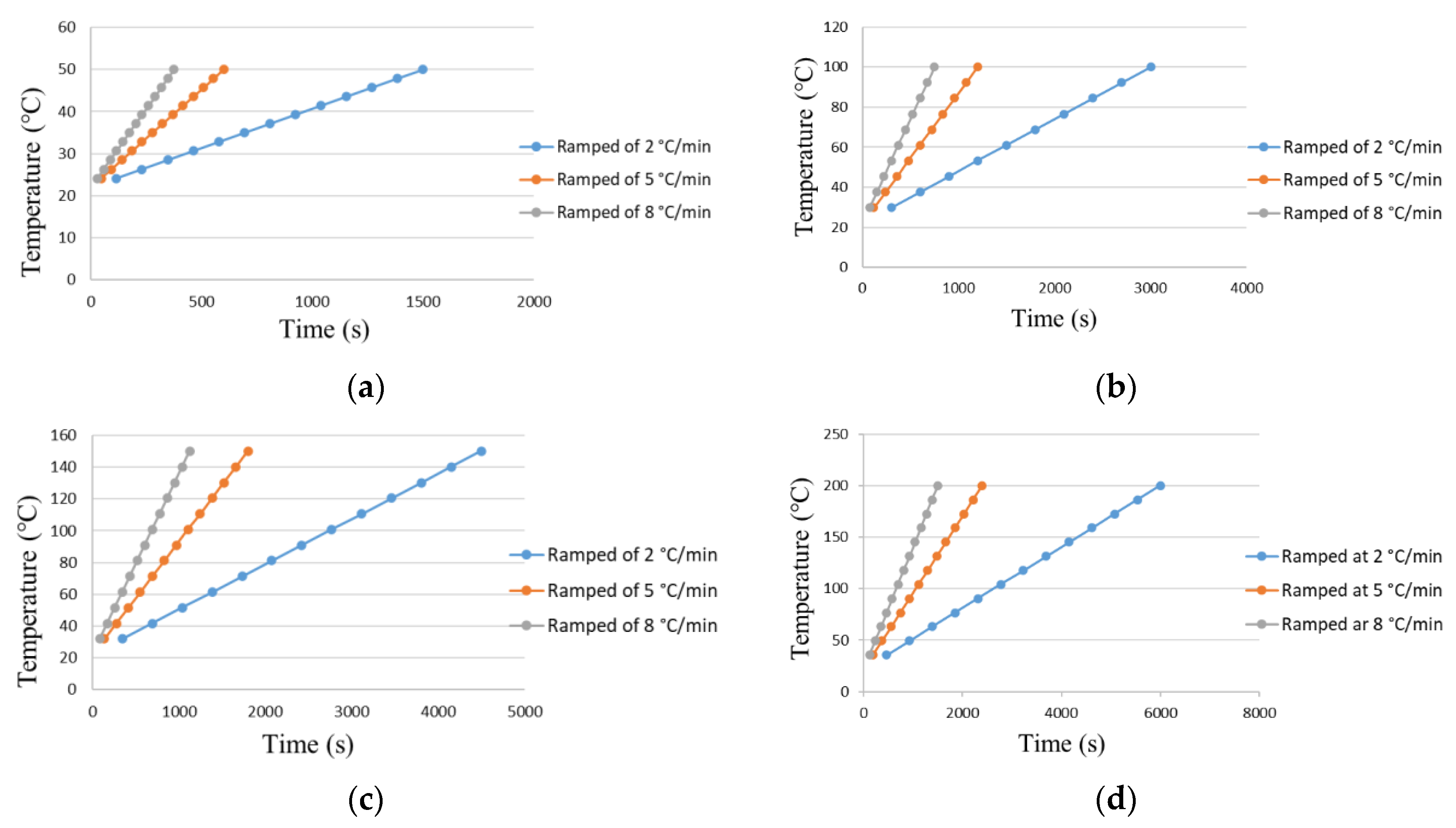
In this research, three cases of heating rate were considered to analyse the effect of temperature exposure time on modal parameters. In the first case, the beam temperature was allowed to increase in a slow and steady rate of 2 °C/min. This enabled the beam to be exposed to the temperature for a longer duration in order to reach the test temperatures. In the second case, the temperature was increased at the rate of 5 °C/min. This heating rate was considered as a moderate rate to reach the required temperature for the experiments. In the third case, the beam temperature was allowed to increase rapidly at the rate of 8 °C/min. This controlled rate of heating the beam was achieved by using a PID temperature controller. Therefore, the temperature along the beam was controlled to meet the experimental requirements. Figure 7a–d presents the time required for all the three cases for the temperature of 50, 100, 150, and 200 °C, respectively. The graphs show that the same temperature was achieved at different times. This means the increase in temperature at the rate of 2 °C/min takes more time to heat the beam for all isothermal conditions. The heating at the rate of 2 °C/min (i.e., slow heat rate) may adversely affect the material properties. It takes more time to reach the required temperature compared to medium and fast heating rates. Therefore, during a slow heating rate, the heat accumulates on the beam for a longer duration and hence has a tendency to influence the material properties more such as reducing the stiffness.
5.2. Impact of Temperature on Modal Parameters without Seeded Crack
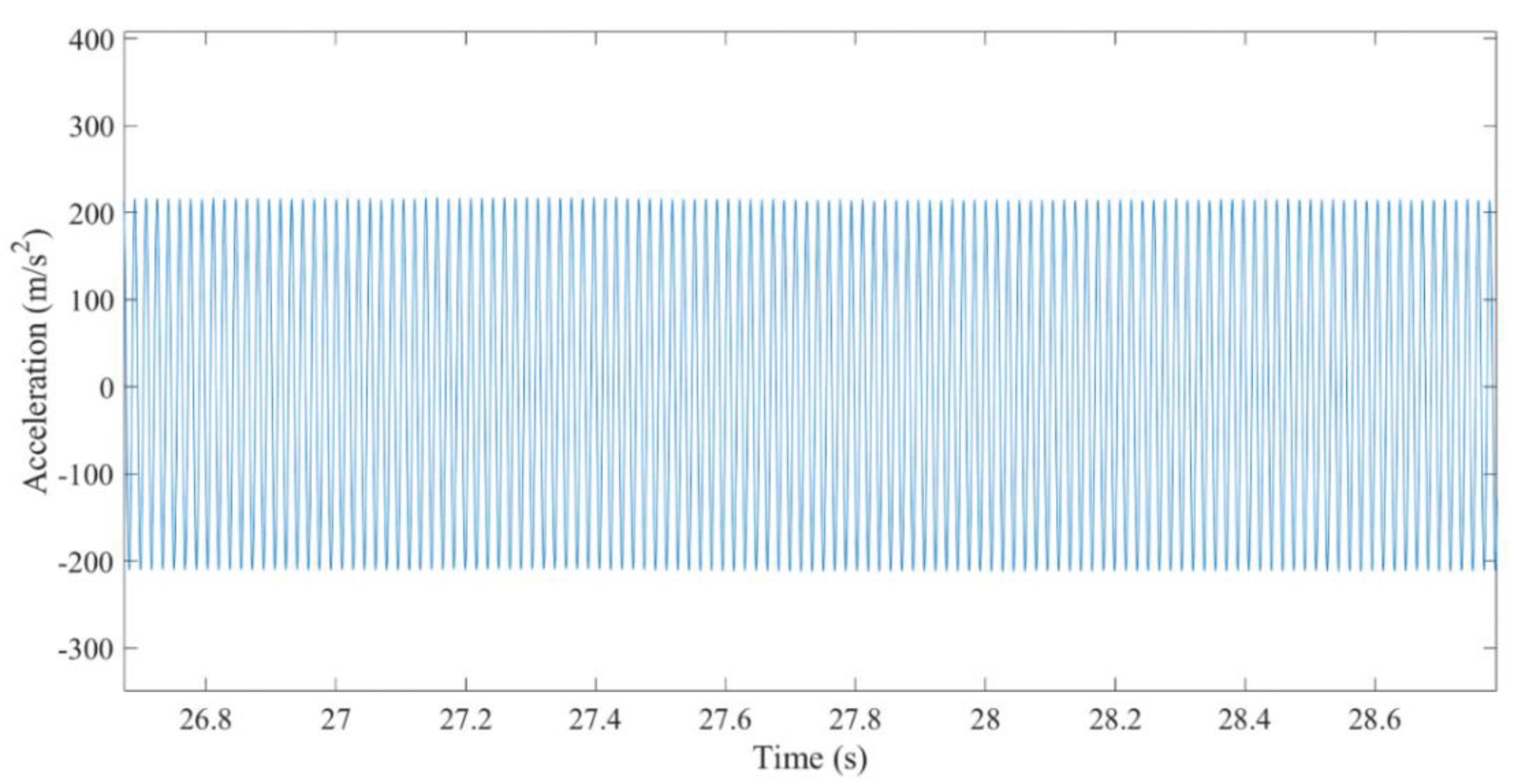
Figure 8 presents the result of the impact test to find the fundamental frequency at 200 °C. While Figure 9 represents the modal amplitude of the specimen running at its fundamental frequency at 200 °C. In order to remove the possibility of error in measurements, a total of three experiments were performed and averaged to get the natural frequency and modal amplitude at a given temperature. All the measurements of the modal response of the specimens were taken while the temperature was maintained at the required level. The temperature along the beam was heated at different temperature rates to investigate the dynamics response accordingly. The comparisons of experimental results of ramped temperature at 2, 5, and 8 °C/min with the numerical and analytical results are presented.
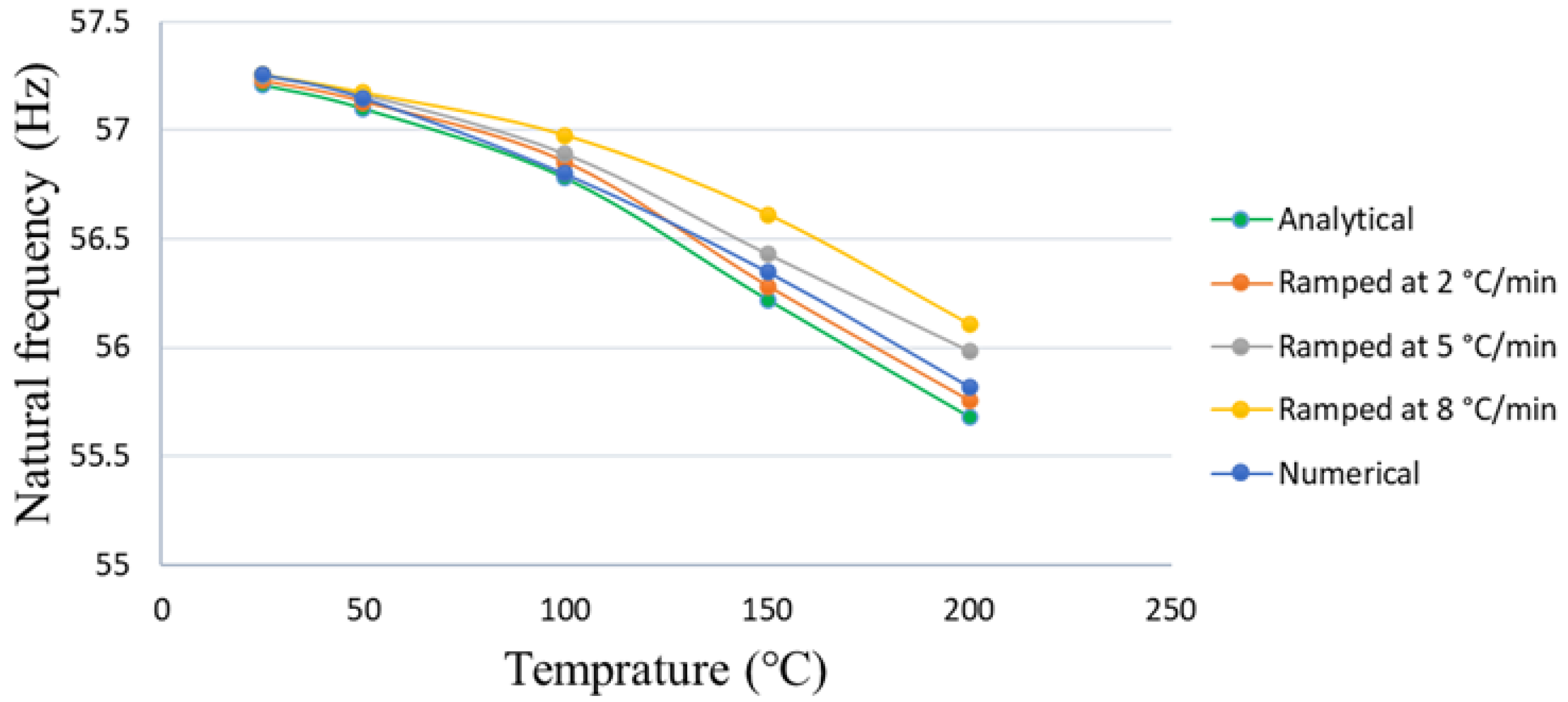
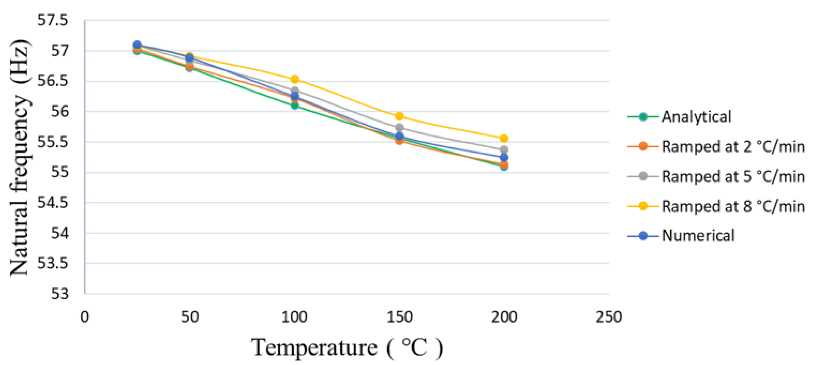
Figure 10 presents the comparison of natural frequency for different heating rates for the specific temperature. The graph suggests that the beam natural frequency decreased with an increase in temperature. This implies that the temperature on the beam surface deteriorated the beam stiffness to a certain level. Moreover, ramping of temperature at different rates had some effect on the beam natural frequency. Ramping of temperature at the rate of 2 °C/min had more impact on natural frequency by diminishing its frequency. However, ramping at 5 and 8 °C/min had little influence compared to ramping at 2 °C/min. This effect of ramping temperature was more significant for higher temperatures as shown in Figure 10. This means that heating at 2 °C/min took more time to reach the desired temperature as shown in Figure 7, thereby accumulating the heat on the beam for a longer duration which might have softened the material properties. This could be explained as changes in interatomic bond length especially at higher temperatures as suggested in [10]. Nevertheless, experimental results of 2 °C/min cases are very close to the numerical and analytical results for all the temperature values.
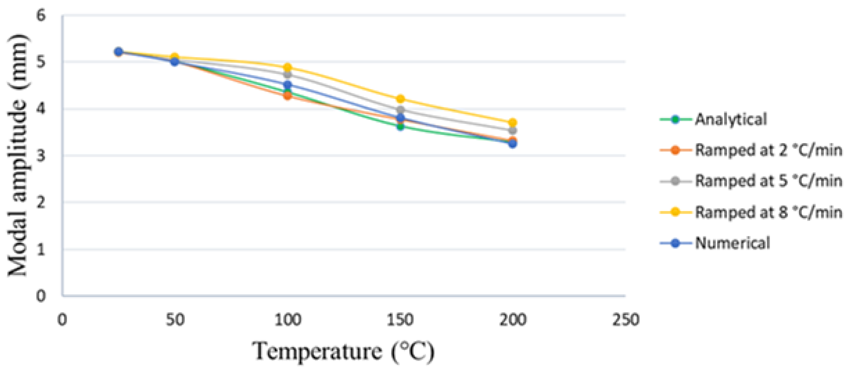
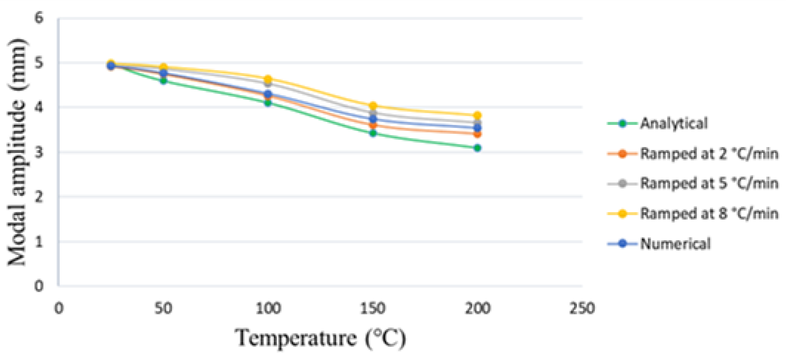
The modal amplitude for different temperatures is shown in Figure 11. The graph illustrates that the amplitude decayed as the temperature increased. The drop in amplitude was associated with the beam’s fundamental frequency. Therefore, the modal amplitude displayed a heating effect similar to the fundamental frequency. The heating rate at 2 °C/min showed lower vibration amplitude compared to the others. This indicates structures went through a more elastic behaviour at higher heating rates. This influence of heating rate was quite visible at high temperature values as shown in Figure 11.
5.3. Impact of Temperature on Modal Parameters in Seeded Crack Specimens
The impact of temperature for three crack depths 0.25, 0.50, and 1 mm were chosen for this assessment. The experimental procedures are the same for all the crack specimens as those without cracks. The natural frequency for 0.25, 0.5, and 1 mm crack depths are shown in Figure 12, Figure 13 and Figure 14, respectively. All the graphs show a similar trend of decreasing frequency with the increase in temperature. Moreover, the trend of decaying is lesser at lower temperatures while deeper trends were observed at higher temperatures. This suggested that the material properties deteriorated at higher temperatures, meaning less elastic. These changes in the material properties were associated with the stiffness of the material at different temperatures.
The rate of heating the specimens had little impact on the fundamental frequency. This research aims to verify this by ramping at 2, 5, and 8 °C/min for all three crack depths. Thus, the effect of the heating rates was compared for all the specimens as shown in respective figures. It is seen that the analytical and numerical results were comparable to the ramping at 2 °C/min. Although, this effect is minimal at lower temperatures and more noticeable at higher temperatures. Therefore, this signifies that the rate of heating can have a slight effect on the dynamic response of any mechanical system.
The effect of temperature on modal amplitude is plotted for all the crack depths. The modal behaviour of 0.25, 0.5, and 1 mm crack depths are shown in Figure 15, Figure 16 and Figure 17, respectively. It was noticed that modal amplitude decreased with the increase in crack depth. The decrease in amplitude was also associated with a rise in temperature. Comparatively, the declining trend of amplitude behaviour for a 1 mm crack depth was more linear than 0.25 and 0.5 mm crack depths. This signified that the increase in crack depth reduced the beam stiffness. Thus, this evidence can be utilized for determining crack depth in structuring health monitoring. It was observed that vibration amplitude was different on all heating rates. The effect of heating rate on amplitude is obvious for higher temperatures. The vibration behaviour of a 0.25 mm crack depth was observed linear till 100 °C. A nonlinear response for all higher temperature ranges was also observed. Similarly, a 0.5 mm crack depth showed a small drop in vibrating amplitude from 25 to 100 °C, and then it dropped abruptly. This implied that the specimen loses its stiffness greatly when the temperature goes above 100 °C. Moreover, a 1 mm crack depth showed a linear response at all values of temperatures. Thus, a 1 mm crack depth was a special case where its stiffness played a bigger role in the vibrating behaviour than the temperature as shown in Figure 17. Heating at 2, 5, and 8 °C/min appeared to have a similar response but heating at 5 and 8 °C/min are small in amplitude drop compared to heating at 2 °C/min. This indicated ramping at 2 °C/min had accumulated more heat on the beam as it takes a longer duration to heat to the required temperature and through this process softens the material properties. Nevertheless, ramping at 2 °C/min is in good agreement with the analytical and numerical results. This signified that heating at a lower rate is more accurate for theoretical and experimental vibration testing.
6. Conclusions
This research studied the modal characteristic of a cantilever beam at three heating rates for isothermal temperature conditions. It was performed as slow heating at 2 °C/min, moderate heating at 5 °C/min, and fast heating at 8 °C/min to analyse the modal response for both with crack and without crack specimens. It was observed that different heating rates have little influence on modal parameters. This impact of heating rates on dynamic response is negligible at lower temperatures and appeared significant at elevated temperatures. The results of different heating rates were compared to the analytical and numerical results. It was found that the results of heating at 2 °C/min appeared close to the analytical and numerical results. This signifies heating at a lower rate is more accurate for any experimental analysis. This also suggested that heating at different rates can have a slight effect while measuring the dynamic response of any mechanical system. The modal frequency and amplitude of the cantilever beam decrease with an increase in temperature in both with crack and without crack specimens. The results showed that modal parameters of the cantilever beam are associated with the change in temperatures and heating rate. Heating at a slower rate takes more time to reach the required temperatures and possibly makes the beam less stiff, especially at elevated temperatures.
Author Contributions
K.K., Conceptualization; Data Curation; Formal Analysis; Investigation; Methodology; Software; Validation; Visualization; Original Draft and Editing. M.A.K., Conceptualization; Formal Analysis; Investigation; Methodology; Supervision; Visualization and Review. K.A.K., Investigation; Methodology; Review and Editing. All authors have read and agreed to the published version of the manuscript.
Funding
This research received no external funding.
Institutional Review Board Statement
Not applicable.
Informed Consent Statement
Not applicable.
Data Availability Statement
Not applicable.
Conflicts of Interest
The authors declare no conflict of interest.
References
- Kamei, K.; Khan, M.A. Current challenges in modelling vibrational fatigue and fracture of structures: A review. J. Braz. Soc. Mech. Sci. Eng. 2021, 43. [Google Scholar] [CrossRef]
- Zai, B.A.; Khan, M.A.; Mansoor, A.; Khan, S.Z.; Khan, K.A. Instant dynamic response measurements for crack monitoring in metallic beams. Insight Non-Destr. Test. Cond. Monit. 2019, 61, 222–229. [Google Scholar] [CrossRef]
- Zai, B.A.; Khan, M.A.; Khan, K.A.; Mansoor, A.; Shah, A.; Shahzad, M. The role of dynamic response parameters in damage prediction. Proc. Inst. Mech. Eng. Part C J. Mech. Eng. Sci. 2019, 233, 4620–4636. [Google Scholar] [CrossRef] [Green Version]
- Warminska, A.; Manoach, E.; Warminski, J.; Samborski, S. Regular and chaotic oscillations of a Timoshenko beam subjected to mechanical and thermal loadings. Contin. Mech. Thermodyn. 2015, 27, 719–737. [Google Scholar] [CrossRef] [Green Version]
- Yang, J.; Shen, H.-S. Vibration characteristics and transient response of shear-deformable functionally graded plates in thermal environments. J. Sound Vib. 2002, 255, 579–602. [Google Scholar] [CrossRef]
- Tornabene, F. Free vibration analysis of functionally graded conical, cylindrical shell and annular plate structures with a four-parameter power-law distribution. Comput. Methods Appl. Mech. Eng. 2009, 198, 2911–2935. [Google Scholar] [CrossRef]
- Ghayesh, M.H.; Kazemirad, S.; Darabi, M.A.; Woo, P. Thermo-mechanical nonlinear vibration analysis of a spring-mass-beam system. Arch. Appl. Mech. 2012, 82, 317–331. [Google Scholar] [CrossRef]
- Julien, B.; Bertrand, F.; Thierry, Y. Probabilistic Random Vibration Fatigue. Procedia Eng. 2013, 66, 522–529. [Google Scholar] [CrossRef] [Green Version]
- Khan, K.A.; Muliana, A.H.; Rajagopal, K.R.; Wineman, A. On viscoelastic beams undergoing cyclic loading: Determining the onset of structural instabilities. Int. J. Non. Linear. Mech. 2018, 99, 40–50. [Google Scholar] [CrossRef]
- Cao, G.; Chen, X.; Kysar, J.W. Thermal vibration and apparent thermal contraction of single-walled carbon nanotubes. J. Mech. Phys. Solids 2006, 54, 1206–1236. [Google Scholar] [CrossRef]
- Khan, M.A.; Khan, S.Z.; Sohail, W.; Khan, H.; Sohaib, M.; Nisar, S. Mechanical fatigue in aluminium at elevated temperature and remaining life prediction based on natural frequency evolution. Fatigue Fract. Eng. Mater. Struct. 2015, 38, 897–903. [Google Scholar] [CrossRef]
- Ebrahimi, F.; Jafari, A. Thermo-mechanical vibration analysis of temperature-dependent porous FG beams based on Timoshenko beam theory. Struct. Eng. Mech. 2016, 59, 343–371. [Google Scholar] [CrossRef]
- Ebrahimi, F.; Farazmandnia, N. Thermo-mechanical vibration analysis of sandwich beams with functionally graded carbon nanotube-reinforced composite face sheets based on a higher-order shear deformation beam theory. Mech. Adv. Mater. Struct. 2017, 24, 820–829. [Google Scholar] [CrossRef]
- Ebrahimi, F.; Ghasemi, F.; Salari, E. Investigating thermal effects on vibration behavior of temperature-dependent compositionally graded Euler beams with porosities. Meccanica 2016, 51, 223–249. [Google Scholar] [CrossRef]
- Ebrahimi, F.; Salari, E.; Hosseini, S.A.H. In-plane thermal loading effects on vibrational characteristics of functionally graded nanobeams. Meccanica 2016, 51, 951–977. [Google Scholar] [CrossRef]
- Zhang, W.; Chen, H.; Zhu, D.; Kong, X. The thermal effects on high-frequency vibration of beams using energy flow analysis. J. Sound Vib. 2014, 333, 2588–2600. [Google Scholar] [CrossRef]
- Cui, D.F.; Hu, H.Y. Thermal buckling and natural vibration of the beam with an axial stick–slip–stop boundary. J. Sound Vib. 2014, 333, 2271–2282. [Google Scholar] [CrossRef]
- Santos Silva, A.C.; Sebastian, C.M.; Lambros, J.; Patterson, E.A. High temperature modal analysis of a non-uniformly heated rectangular plate: Experiments and simulations. J. Sound Vib. 2019, 443, 397–410. [Google Scholar] [CrossRef]
- Ghadiri, M.; Shafiei, N.; Alavi, H. Thermo-mechanical vibration of orthotropic cantilever and propped cantilever nanoplate using generalized differential quadrature method. Mech. Adv. Mater. Struct. 2017, 24, 636–646. [Google Scholar] [CrossRef]
- Fazzolari, F.A. Modal characteristics of P- and S-FGM plates with temperature-dependent materials in thermal environment. J. Therm. Stress. 2016, 39, 854–873. [Google Scholar] [CrossRef]
- Kawamura, R.; Tanigawa, Y.; Kusuki, S.; Hamamura, H. Fundamental thermo-elasticity equations for thermally induced flexural vibration problems for inhomogeneous plates and thermo-elastic dynamical responses to a sinusoidally varying surface temperature. J. Eng. Math. 2008, 61, 143–160. [Google Scholar] [CrossRef]
- Attar, M. A transfer matrix method for free vibration analysis and crack identification of stepped beams with multiple edge cracks and different boundary conditions. Int. J. Mech. Sci. 2012, 57, 19–33. [Google Scholar] [CrossRef]
- Baqasah, H.; He, F.; Zai, B.A.; Asif, M.; Khan, K.A.; Thakur, V.K.; Khan, M.A. In-situ dynamic response measurement for damage quantification of 3D printed ABS cantilever beam under thermomechanical load. Polymers 2019, 11, 2079. [Google Scholar] [CrossRef] [Green Version]
- He, F.; Thakur, V.K.; Khan, M. Evolution and new horizons in modeling crack mechanics of 3D printing polymeric structures. Mater. Today Chem. 2021, 20. [Google Scholar] [CrossRef]
- Fleet, T.; Kamei, K.; He, F.; Khan, M.A.; Khan, K.A.; Starr, A. A machine learning approach to model interdependencies between dynamic response and crack propagation. Sensors 2020, 20, 6847. [Google Scholar] [CrossRef] [PubMed]
- Khan, M.A.; Khan, K.A.; Khan, S.Z.; Nisar, S.; Starr, A. Fracture life estimation of Al-1050 thin beams using empirical data and a numerical approach. Insight Non-Destr. Test. Cond. Monit. 2018, 60, 363–368. [Google Scholar] [CrossRef] [Green Version]
- Zai, B.A.; Khan, M.A.; Khan, S.Z.; Asif, M.; Khan, K.A.; Saquib, A.N.; Mansoor, A.; Shahzad, M.; Mujtaba, A. Prediction of crack depth and fatigue life of an acrylonitrile butadiene styrene cantilever beam using dynamic response. J. Test. Eval. 2020, 48. [Google Scholar] [CrossRef]
- Fernández-Sáez, J.; Rubio, L.; Navarro, C. Approximate calculation of the fundamental frequency for bending vibrations of cracked beams. J. Sound Vib. 1999, 225, 345–352. [Google Scholar] [CrossRef]
- Narkis, Y.; Elmalah, E. Crack identification in a cantilever beam under uncertain end conditions. Int. J. Mech. Sci. 1996, 38, 499–507. [Google Scholar] [CrossRef]
- Lin, H.P. Direct and inverse methods on free vibration analysis of simply supported beams with a crack. Eng. Struct. 2004, 26, 427–436. [Google Scholar] [CrossRef]
- Rizos, P.F.; Aspragathos, N.; Dimarogonas, A.D. Identification of crack location and magnitude in a cantilever beam from the vibration modes. J. Sound Vib. 1990, 138, 381–388. [Google Scholar] [CrossRef]
- Li, S.C.; Liang, L.; Yu, Q. Natural frequency of bending vibration for stepped beam of different geometrical characters and materials. Noise Vib. Worldw. 2019, 50, 3–12. [Google Scholar] [CrossRef]
- Elshamy, M.; Crosby, W.A.; Elhadary, M. Crack detection of cantilever beam by natural frequency tracking using experimental and finite element analysis. Alex. Eng. J. 2018, 57, 3755–3766. [Google Scholar] [CrossRef]
- Altunışık, A.C.; Okur, F.Y.; Kahya, V. Modal parameter identification and vibration based damage detection of a multiple cracked cantilever beam. Eng. Fail. Anal. 2017, 79, 154–170. [Google Scholar] [CrossRef]
- Zai, B.A.; Khan, M.A.; Khan, K.A.; Mansoor, A. A novel approach for damage quantification using the dynamic response of a metallic beam under thermo-mechanical loads. J. Sound Vib. 2020, 469. [Google Scholar] [CrossRef]
- Courtney, T.H. Mechanical Behavior of Materiasl; Waveland Press, Inc.: Long Grove, IL, USA, 2000; ISBN 9781577664253. [Google Scholar]
- Akbarzadeh Khorshidi, M.; Soltani, D. Diagnosis of Type, Location and Size of Cracks by Using Generalized Differential Quadrature and Rayleigh Quotient Methods. J. Theor. Appl. Mech. 2013, 43, 61–70. [Google Scholar] [CrossRef] [Green Version]
- Barron, R.F.; Barron, B.R. Design for Thermal Stresses; John Wiley & Sons, Inc.: Hoboken, NJ, USA, 2012; ISBN 9780470627693. [Google Scholar]
Figure 1.
(a) Cantilever beam; (b) free body diagram for beam element.

Figure 2.
(a) Experiment specimens; (b) no crack specimen geometry.

Figure 3.
Experimental scheme.

Figure 4.
Experimental layout.

Figure 5.
Experimental set-up.

Figure 6.
ANSYS© model showing the results.

Figure 7.
Temperature exposure duration for (a) 50 °C; (b) 100 °C; (c) 150 °C; (d) 200 °C.

Figure 8.
Determined natural frequency at 200 °C.

Figure 9.
The determined modal amplitude at 200 °C.

Figure 10.
Natural frequency for an uncracked beam.

Figure 11.
Modal amplitude for an uncracked beam.

Figure 12.
Natural frequency for a 0.25 mm crack depth.

Figure 13.
Natural frequency for a 0.50 mm crack depth.

Figure 14.
Natural frequency for a 1 mm crack depth.

Figure 15.
Modal amplitude for a 0.25 mm crack depth.

Figure 16.
Modal amplitude for a 0.50 mm crack depth.

Figure 17.
Modal amplitude for a 1 mm crack depth.


Table 1.
Thermal properties of Al 2024-T3 at different temperatures.
| Temperature (°C) | Elastic Modulus (E) GPa | ||
|---|---|---|---|
| 25 | 73.4 | 0.1066 | 0.1136 |
| 50 | 72.7 | 0.1078 | 0.1180 |
| 100 | 69.3 | 0.1091 | 0.1260 |
| 150 | 68.5 | 0.1266 | 0.1287 |
| 200 | 65.2 | 0.1359 | 0.1309 |
Table 2.
Chemical composition of Al 2024-T3.
| Chemical | Si | Fe | Mn | Mg | Cr | Zn | Ti | V | Other |
|---|---|---|---|---|---|---|---|---|---|
| Actual (wt %) | 0.07 | 0.18 | 4.4 | 0.58 | 1.3 | 0.01 | 0.13 | 0.02 | 0.02 |
Publisher’s Note: MDPI stays neutral with regard to jurisdictional claims in published maps and institutional affiliations. |
© 2021 by the authors. Licensee MDPI, Basel, Switzerland. This article is an open access article distributed under the terms and conditions of the Creative Commons Attribution (CC BY) license (https://creativecommons.org/licenses/by/4.0/).
Share and Cite
MDPI and ACS Style
Kamei, K.; Khan, M.A.; Khan, K.A. Characterising Modal Behaviour of a Cantilever Beam at Different Heating Rates for Isothermal Conditions. Appl. Sci. 2021, 11, 4375. https://doi.org/10.3390/app11104375
AMA Style
Kamei K, Khan MA, Khan KA. Characterising Modal Behaviour of a Cantilever Beam at Different Heating Rates for Isothermal Conditions. Applied Sciences. 2021; 11(10):4375. https://doi.org/10.3390/app11104375
Chicago/Turabian StyleKamei, Khangamlung, Muhammad A. Khan, and Kamran A. Khan. 2021. "Characterising Modal Behaviour of a Cantilever Beam at Different Heating Rates for Isothermal Conditions" Applied Sciences 11, no. 10: 4375. https://doi.org/10.3390/app11104375
Note that from the first issue of 2016, this journal uses article numbers instead of page numbers. See further details here.