Simply supported beam: Moment and Shear hand calculation
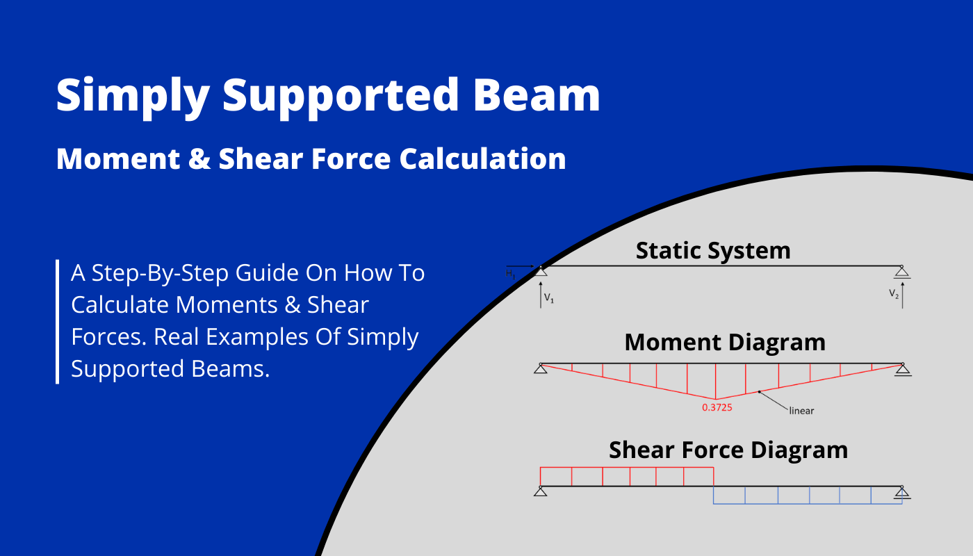
As we used FE programs to calculate the bending moments, shear forces and deflections of structures in last tutorials, we are going a step back now to the very basics of structural engineering and do hand calculations.
After starting this new series of posts with the cantilever beam, we continue our journey with the probably most used static system – the simply supported beam.
We’ll show, step-by-step, how the probably most used formula in structural engineering
$$M=q\cdot l^2/8$$
is derived and how to calculate the bending moments and shear forces for different loading situations.
Not much more talk, let’s get started.
🙋♀️ What is a simply supported beam?
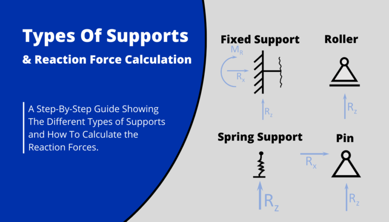
A simply supported beam is a static system acting as a beam element in bending and shear – in some situations also compression or tension due to axial forces. It’s characterized by having two supports, a roller and a pinned support. Those supports allow for rotation.
We are surrounded by simply supported beams in our daily lives.
Here are 7 examples of simply supported beams in real life
- One span precast concrete beam
- One span precast concrete slab
- One span bridge deck supported by bearings
- Timber flat roof with secondary beams
- One span steel beam
- Rafter beams supported by 2 Purlin beams
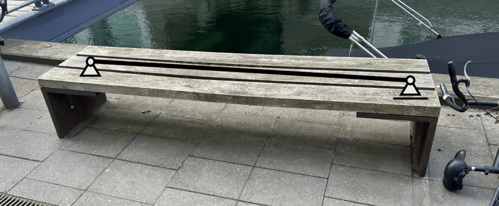
- Benches supported on both ends (Example in the following)
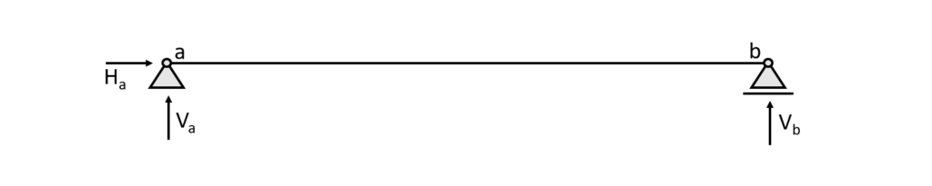
👆 The static system of the simply supported beam
The simply supported beam is in most cases a horizontal beam having a roller and a pinned support on the ends. The beam can take normal and shear forces as well as bending moments.
Let’s have a look at the static system.
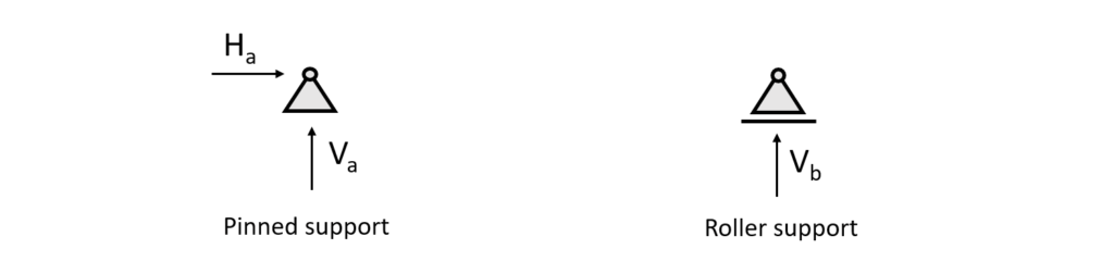
It can be seen from the picture that the pinned support (a) takes up
- a vertical reaction force $V_a$ and
- a horizontal reaction force $H_a$
The roller support (b) takes up
- a vertical reaction force $V_b$
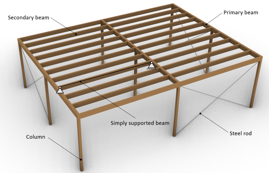
🏢 The simply supported beam applied on real structures
Understanding the static system of a structure is probably one of the hardest parts about statics and structural engineering in the beginning.
From my experience it’s also poorly taught at university and there is very little information about it online as well, isn’t it?
So let’s look at some applied examples.
- The secondary beams of a flat roof. Note that the primary beams can also be simply supported. In our example only the secondary beams are simply supported.
- The wooden beams/panels of this bench are simply supported.
⬇️ 2 Examples of loading situations
We wanna keep it a bit joyful and realistic in this blog, right? So let’s look at loading scenarios we all can relate to.
🧍 Me sitting and meditating on a bench – A Point load
Let’s look at the example where a person – in this case me😊 – sits on bench and meditates🧘♂️. Let’s assume i gained a little bit of weight compared to the last tutorial and now i weigh 76 kg.

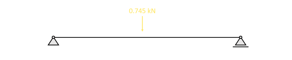
This weight of 76 kg can directly be translated into 0.745 kN.
Now because I sit in a specific point with my butt, the load is concentrated and therefore the 0.745 kN can be approximated as a point load on the simply supported beam(s).
❗So be always aware of your approximations and consider if they are applicable for what you want to achieve.
As we want to demonstrate a “real-life” example of a point load, this point load is not 100% realistic.
However, there are almost no “100%-correct” point loads and a person sitting on a bench comes close enough to a point load applied to a bench for dimensioning the thickness and width of the timber beam.
Alright, let’s get back to the beam model.
The 3 beams of the bench equal 1 beam when we calculate moments and shear forces with this simple approach.
We can therefore apply the Point load on the static system of the simply supported beam.
🏋️ The self-weight of a timber beam – Line load
So, the timber beam has a self-weight, right? I guess everyone can image that when you try to lift it up.
In structural engineering, we also call this dead load, and it’s always equally/uniformly distributed for horizontal elements.
For the case of the timber secondary beam, the self-weight per $m$ is calculated as
$\mbox{Density} \, \rho \cdot \mbox{Cross-sectional Area A} \,$
The density of timber beams is found either from manufacturer tables online or Standards.
The cross-sectional area of the timber beam is taken from the previous article, where we designed the flat roof and its beams.
$\rho = 380 \mbox{kg/m}^3$
$A = h \cdot w = 28800 \mbox{mm}^2$
$380 \mbox{kg/m}^3 \cdot 28800 \mbox{mm}^2 = 0.11 \mbox{kN/m}$
Now, it always helps to translate kN in non-engineering language. $0.11$ kN/m is also 10.9 kg per $m$.
That’s roughly as much as a French bulldog dog – but per meter and per beam! So in case of our timber beam where we have a span of $5m$ the dead load of the wood is equal to 5 dogs🐕.

This line load (kN/m) – or those 5 dogs – can now also be applied to the simply supported beam.

🧮 Hand calculation of bending moment and shear forces – simply supported beam
Now in order to design the thickness and material properties of the bench, the secondary beam – or any other simply supported structure the forces and moments acting in the beam need to be calculated.
In general, statically determinate structures such as the cantilever or the simply supported beams need to fullfill three equilibrium conditions:
- Horizontal equilibrium $\sum H = 0$: The sum of all horizontal loads and reactions is 0.
- Vertical equilibrium $\sum V = 0$: The sum of all vertical loads and reactions is 0.
- Moment equilibrium $\sum M = 0$: The sum of all moments is 0.
Let’s continue with the 2 loading situations that we are now familiar with – point and line load.
🔎 Bending moment and shear forces of a beam – Point load on bench
1. The first thing we always calculate in determinate structures are the reaction forces/moment. In our case that is $V_a, H_a$ at support (a) and $V_b$ at support (b) due to the equilibrium conditions.
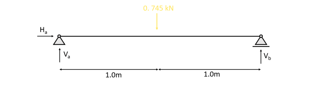
$\sum H = 0: H_a = 0$
$\sum V = 0: V_a + V_b – 0.745 \mbox{kN}= 0 =$ -> $V_a = V_b = \frac{0.745}{2} \mbox{kN} = 0.3725 \mbox{kN}$
$\sum M = 0: M_a = 0$
2. Calculation of the shear and moment distribution along the beam due to the reaction forces. The parameter x is introduced as the length between point a and any point on the beam.
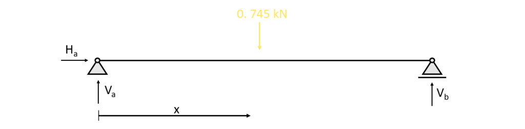
3. The shear forces and bending moments can be calculated in dependence of x. Let’s make a first cut at a point between the support and the point load 0<x<1.0m.

As for the reaction force calculation, the equilibrium conditions are used to calculate the moment and shear forces at point x
$\sum H = 0: H_a = 0$
$\sum V = 0: 0.3725 \mbox{kN} – V_x = 0$ -> $V_x = 0.3725 \mbox{kN}$
$\sum M = 0: M_x – 0.3725 \mbox{kN} \cdot x = 0$ -> $M_x = 0.3725 \mbox{kN} \cdot x$
As we can see the shear force is constant and not dependent on the parameter x. Let’s set x = 1.0m and see what results we get for the bending moment:
$M_{1.0m} = 0.3725 \mbox{kN} \cdot 1.0m = 0.3725 \mbox{kNm}$
In dependence of x and the Point load Q = 0.745kN a general formula for the bending moment of a simply supported beam for 0<x<l/2 can be formulated as:
$M_{x} = 1/2 \cdot Q \cdot x$
You might have already come across the formula when we set x=l/2
$M_{max} = 1/2 \cdot Q \cdot l/2 = 1/4 \cdot Ql$
4. Cut at a point between the point load and the endpoint 1.0m<x<2.0m

The equilibrium conditions lead to
$\sum H = 0: H_a = 0$
$\sum V = 0: 0.3725 kN – V_x – 0.745 kN = 0$ -> $V_x = -0.3725 kN$
$\sum M = 0: M_x – 0.3725 kN \cdot x + 0.745 kN \cdot (x-1.0m) = 0$
$M_x = 0.3725 kN \cdot x – 0.745 kN \cdot x + 0.745 kNm = -0.3725 kN \cdot x + 0.745 kNm$

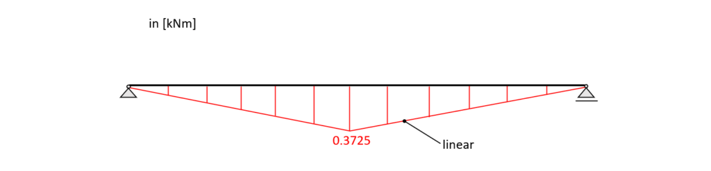
5. Bending moment and shear force diagrams
The diagrams can be plotted by a tool like Excel using the formulas from above or drawn by hand when one is aware of the geometrical shape of the distribution.
Shear force diagram – simply supported beam

Bending moment diagram – simply supported beam
👨🏫 Bending moment and shear forces of a beam – Line load on the secondary roof beam
1.As for the Point load, we first calculate the reaction forces $V_a, H_a$ and moment $M_a$ in the determinate structure – simply supported beam – due to the equilibrium conditions.

$\sum H = 0: H_a = 0$
$\sum V = 0: V_a + V_b – 0.11 \mbox{kN/m} \cdot 5.0m = 0$ -> $V_a = 0.5 \cdot 0.11 \mbox{kN/m} \cdot 5\mbox{m} = 0.275 \mbox{kN}$
$\sum M = 0: M_a = M_b = 0$
2. Calculation of the shear and moment distribution along the beam due to the reaction forces. The parameter x is introduced as the length between point a and any point on the beam.

3. The shear forces and bending moments can be calculated in dependence of x. Let’s make a cut at a point between the support a and support b 0<x<5.0m.
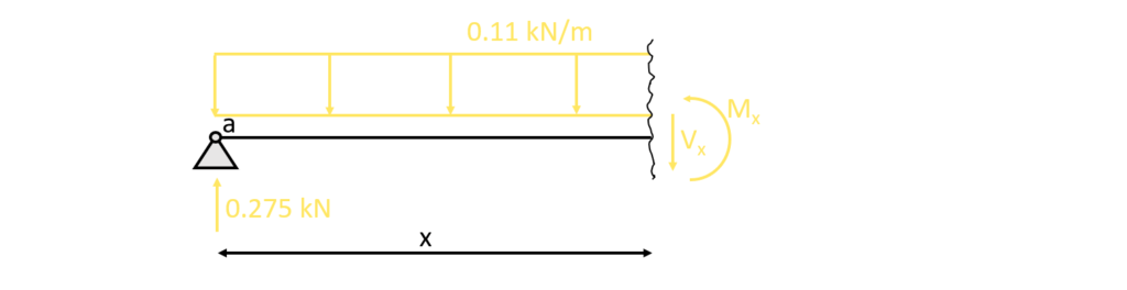
As for the reaction force calculation, the equilibrium conditions are used to calculate the moment and shear forces at point x.
$\sum H = 0: H_a = 0$
$\sum V = 0: V_x + 0.11 \mbox{kN/m} \cdot x – 0.275 \mbox{kN} = 0$ -> $V_x = 0.275\mbox{kN} – 0.11 \mbox{kN/m} \cdot x$
$\sum M = 0: M_x – 0.275 \mbox{kN} \cdot x + 0.11 \mbox{kN/m} \cdot \frac{x^2}{2} = 0$ -> $M_x = 0.275 \mbox{kN} \cdot x – 0.11 \mbox{kN/m} \cdot \frac{x^2}{2}$
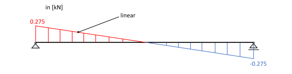
Compared to the distribution due to a point load, the shear force distribution is now linear and dependent on the parameter x.
From the moment formulation, we can now derive the famous formula for the maximum bending moment of a simply supported beam due to a line load. Let’s set x = l/2=2.5m.
Formula for maximum bending moment in simply supported beam $ql^2/8$
In order to get the formula we change the load and reaction values to variables. The line load 0.11kN/m is used as q and the reaction force $V_a$ equals ql/2.
$M_{x} = q \cdot l/2 \cdot x – q \cdot \frac{x^2}{2}$
$M_{l/2} = q \cdot l/2 \cdot l/2 – q \cdot \frac{(l/2)^2}{2} = q \cdot l^{2}/4 – q \cdot \frac{l^2}{8} = q \cdot l^{2}/8$
$M_{l/2} = 0.11 \mbox{kN/m} \cdot (5\mbox{m})^{2}/8 = 0.34 \mbox{kNm}$
Formula for maximum shear force in simply supported beam $ql/2$
As for the bending moment we change the load and reaction values to variables. The line load 0.11kN/m is used as q and the reaction force $V_a$ equals ql/2.
$V_{x} = q \cdot l/2 – q \cdot x $
Now, the maximum shear force acts right next to the supports, therefore x is set to 0, or l
$V_{0} = q \cdot l/2 – 0 $
$V_{0} = 0.11 \mbox{kN/m} \cdot 5\mbox{m}/2 = 0.275\mbox{kN}$
4. Bending moment and shear force diagrams
The diagrams can be plotted by a tool like Excel using the formulas from above or drawn by hand when one is aware of the geometrical shape of the distribution.
Shear force diagram – simply supported beam
Bending moment diagram – simply supported beam

Once the forces and moments are calculated for different load cases like
and loads are combined in load combinations, the design of the element needs to be done.
In our case that is the timber design of the secondary beam, meaning that we pick the timber type, calculate the required cross-sectional dimensions and much more.
We actually calculated the flat roof in full scale in this article.
Now, I would like to hear from you: What simply supported structures do you know from the “real world”? Did I forget some? Let us know in the comments below📝
![Gambrel Truss [A Structural Guide]](https://www.structuralbasics.com/wp-content/uploads/2023/02/Gambrel-truss-768x439.jpg)
![Queen Post Trusses Explained! [2024]](https://www.structuralbasics.com/wp-content/uploads/2023/02/Queen-post-truss-768x439.jpg)
![Arch – Moment And Normal Force Calculation Due To Line Load [A Guide]](https://www.structuralbasics.com/wp-content/uploads/2022/05/Arch-Structure-Internal-Force-Calculation-Due-To-Line-Load-768x439.jpg)